Anti-circumvention enclosure device and construction method for underground diaphragm wall joints

An underground diaphragm wall and construction method technology, applied in artificial islands, water conservancy projects, underwater structures, etc., can solve the problems of manpower, material resources, seam seepage, time-consuming and other problems, saving time, increasing sealing, Ensure the effect of construction quality

Active Publication Date: 2017-12-22
CHINA RAILWAY NO 3 GRP CO LTD
View PDF7 Cites 0 Cited by
  • Summary
  • Abstract
  • Description
  • Claims
  • Application Information

AI Technical Summary

Problems solved by technology

[0004] In order to solve the problem that the traditional underground diaphragm wall joints prevent concrete from flowing around, the external sealing of the I-beam with sand bags is used to fill the outside of the I-beam, which consumes manpower and material resources, takes a long time, and easily causes water seepage in the joints. Diaphragm wall joint anti-flow enclosure device and construction method

Method used


Image

  • Anti-circumvention enclosure device and construction method for underground diaphragm wall joints
  • Anti-circumvention enclosure device and construction method for underground diaphragm wall joints
  • Anti-circumvention enclosure device and construction method for underground diaphragm wall joints

Examples


Embodiment Construction

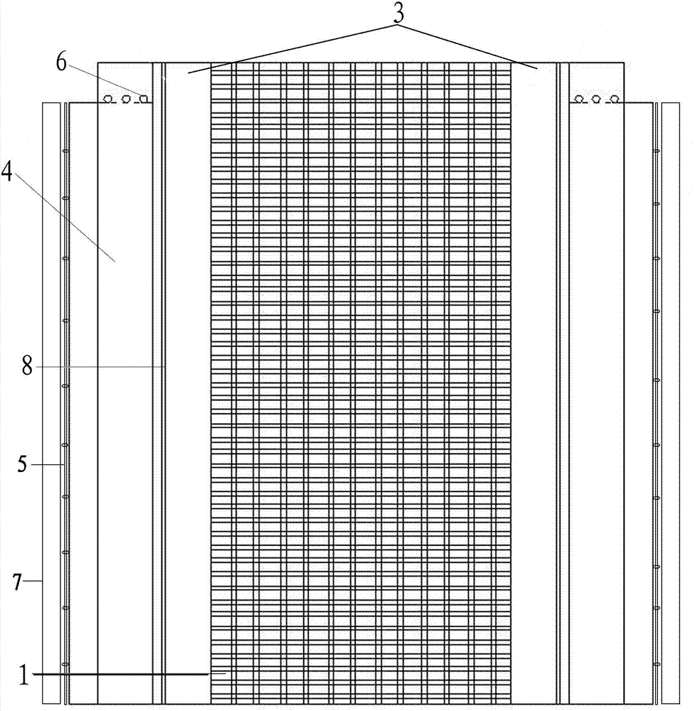
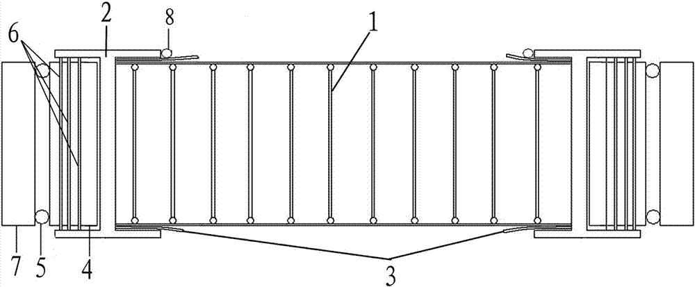
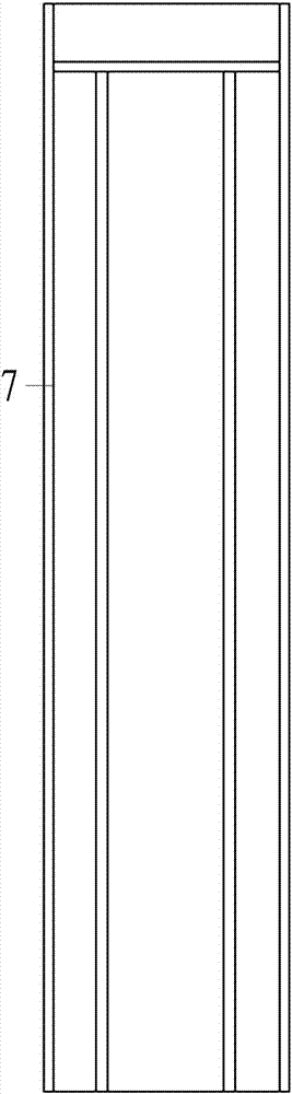
[0022] An underground diaphragm wall joint anti-flow containment device, which is set based on the underground diaphragm wall steel cage 1 and the joint I-beam 2, including the upper part of the inner side of the bottom flange of the joint I-beam 2 and the lower part of the inner side of the top flange The galvanized steel plate 3 welded through the length, the sealing plate 4 bound on the back side of the web of the joint I-beam 2, and the joint box 7 set on the top of the sealing plate 4 and fixed on the guide wall; the galvanized steel plate 3 is placed down During the process, it opens in a trumpet shape, and the outer side of the sealing plate 4 is fixed with two rows of fixing rods 5;

[0023] Along the side edges of the top flange of the joint I-beam 2 and the upper part of the galvanized steel sheet 3, a fixing steel bar 8 for fixing the galvanized steel sheet is smoothly arranged. The sealing plate 4 is a foam board wrapped and sealed with plastic cloth on the outside...


PUM


Abstract

The invention belongs to the technical field of underground diaphragm wall joint construction. In order to solve the problem of traditional underground diaphragm wall joints preventing concrete from flowing around, the outer side of the I-beam is filled with sand bags for external sealing, which consumes manpower and material resources, takes a long time, and the joints are prone to water seepage. Provided are an underground diaphragm wall joint anti-circumvention enclosure device and a construction method. Weld the galvanized steel plate at the upper part of the inner side of the bottom flange of the joint I-beam and the lower part of the inner side of the top flange, bind the sealing plate on the back side of the web of the joint I-beam, and set the seam fixed on the guide wall on the top of the sealing plate Box; the galvanized steel plate opens in the shape of a trumpet during the lowering process, and the two rows of fixing rods outside the sealing plate are fixed; the top of the sealing plate and the joint I-beam upper and lower wing plates are welded with fixing ribs. It is suitable for joint construction of underground diaphragm wall, prevents concrete from flowing around during pouring, ensures joint construction quality, and improves joint shear resistance and anti-leakage capacity. Great operability and strong promotion. Popularized and applied in the construction of underground diaphragm walls, the application is novel and reliable, and the technology is mature and advanced.

Description

technical field [0001] The invention belongs to the technical field of underground continuous wall joint construction, and particularly relates to an underground continuous wall joint anti-circumvention enclosure device and a construction method. Background technique [0002] The hazards of the flow around the joints of the underground diaphragm wall mainly include the following two points: First, if the protruding concrete block is not removed, it will affect the lowering of the reinforcement cage of the lower diaphragm wall, so that the sealing reinforcement of the reinforcement cage cannot be close to the already poured underground. The web of the H-section steel of the continuous wall affects the lap width of the joint. There will be a dead corner under the protruding concrete block that cannot be brushed by the wall brush, and this piece will deposit mud, so that after the two walls are poured, there is a penetration between the two walls. After the foundation pit is ex...

Claims


Application Information

Patent Timeline
Patent Type & Authority Patents(China)
IPC IPC(8): E02D29/16
Inventor 孙伯乐张俊兵郑保才李达昌
Owner CHINA RAILWAY NO 3 GRP CO LTD
Why Eureka
Try Eureka