
Volute type centrifugal fan with one let and two outlets

A centrifugal fan and volute-type technology, applied in the field of volute-type centrifugal fans, can solve the problems that the position cannot be changed, and the medium flow direction cannot be changed again, so as to maintain high wind pressure, realize the secondary reversing requirement, and reduce noise Effect

Inactive Publication Date: 2015-10-07
GUANGDONG PHNIX TECH CO LTD
View PDF5 Cites 20 Cited by
  • Summary
  • Abstract
  • Description
  • Claims
  • Application Information

AI Technical Summary

Problems solved by technology

The traditional centrifugal fan is usually a volute structure. Compared with the straight-in and straight-out axial flow fan, the volute centrifugal fan will change the flow direction of the medium in the fan, but after the position of the air outlet is determined, it is not only impossible to change the position, but also impossible Change the flow direction of the medium again, so for the heat pump water heater with air-conditioning function, when switching between the normal mode and the air-conditioning mode, the flow direction of the medium must be changed to meet the user's needs, but the traditional volute centrifugal fan cannot meet such requirements

Method used


Image

  • Volute type centrifugal fan with one let and two outlets
  • Volute type centrifugal fan with one let and two outlets
  • Volute type centrifugal fan with one let and two outlets

Examples


Embodiment Construction

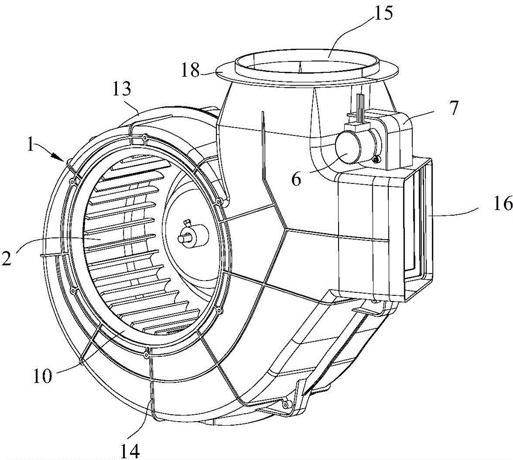
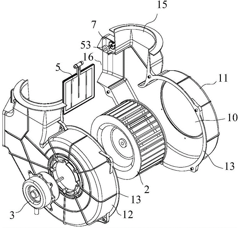
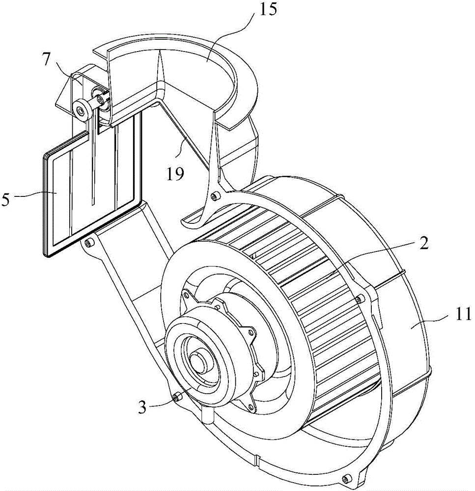
[0020] refer to Figure 1 to Figure 5 , which shows the specific structure of the preferred embodiment of the present invention. The structural characteristics of each element of the present invention will be described in detail below, and if there is a description of the direction (up, down, left, right, front and back), it is based on figure 1 The shown structure is a reference description, but the actual use direction of the present invention is not limited thereto.

[0021] The present invention provides a one-in two-out volute Type centrifugal fan, including a volute 1, a fan blade 2 installed in the volute 1, and a fan motor 3 for driving the fan blade 2, and the volute 1 is provided with an air inlet 10 on the opposite side of the fan blade 2 , the volute 1 includes a front shell 11 and a rear shell 12 that are fastened to each other, and the front shell 11 and the rear shell 12 are provided with a flange 13 on the edge that is fastened to each other, along which sev...


PUM


Abstract

The invention discloses a volute type centrifugal fan with one inlet and two outlets. The volute type centrifugal fan with the inlet and two outlets comprises a volute, blades installed in the volute and a blade motor, wherein the air inlet is formed in the volute; an air cavity is formed inside the volute and on the outer side of the blades; the first air outlet and the second air outlet between which an included angle is formed are formed in the tail of the air cavity of the volute; a reversing baffle is arranged inside the air cavity of the volute and can enable the first air outlet or the second air outlet to be communicated with the air cavity. A new air outlet is additionally arranged at an air outlet of a traditional volute centrifugal fan, and an included angle is formed between the two air outlets, so that when a normal mode and a cold air mode of a heat pump water heater with a cold air function are switched, reversing of media inside the fan needs can be finished as needed by adjusting the reversing baffle. The volute type centrifugal fan with the inlet and two outlets can well meet the requirements of machines. As the automatic switching type reversing baffle is applied to the fan, secondary reversing requirement of the medium inside the centrifugal fan is realized, and the characteristics of high air pressure and low noise of an original centrifugal fan are kept.

Description

technical field [0001] The invention is used in the field of overhead cables, in particular relates to a one-input two-out volute type centrifugal fan. Background technique [0002] At present, the centrifugal fan is applied to the heat pump water heater as a common fan equipment. Compared with the axial flow fan commonly used in the heat pump system, it has the advantages of high wind pressure, low noise, and can change the wind direction. Heat pump water heater. The traditional centrifugal fan is usually a volute structure. Compared with the straight-in and straight-out axial flow fan, the volute centrifugal fan will change the flow direction of the medium in the fan, but after the position of the air outlet is determined, it is not only impossible to change the position, but also impossible Change the flow direction of the medium again, so for the heat pump water heater with air-conditioning function, when switching between the normal mode and the air-conditioning mode,...

Claims


Application Information

Patent Timeline
IPC IPC(8): F04D29/42F04D27/00F04D17/08
CPCF04D29/462F04D29/4246
Inventor 彭玉坤梁晓恩毛萌节
Owner GUANGDONG PHNIX TECH CO LTD
Learn More