
A miniaturized 100-level laminar flow belt

A technology of 100-level laminar flow and air flow, which is applied in the field of small and simplified 100-level laminar flow belt, can solve the problems of one-time investment and high operating costs of 100-level laminar flow belt, reduce the risk of pollution, and increase the speed of construction and dismantling , The effect of reducing heat load

Active Publication Date: 2017-12-26
JIANGSU SUZHOU PURIFICATION TECH
View PDF5 Cites 0 Cited by
  • Summary
  • Abstract
  • Description
  • Claims
  • Application Information

AI Technical Summary

Problems solved by technology

[0005] Again, from the perspective of optimization and energy saving, the one-time investment and operating costs of the 100-level laminar flow belt are still relatively high

Method used

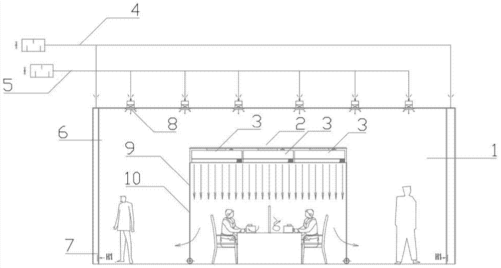
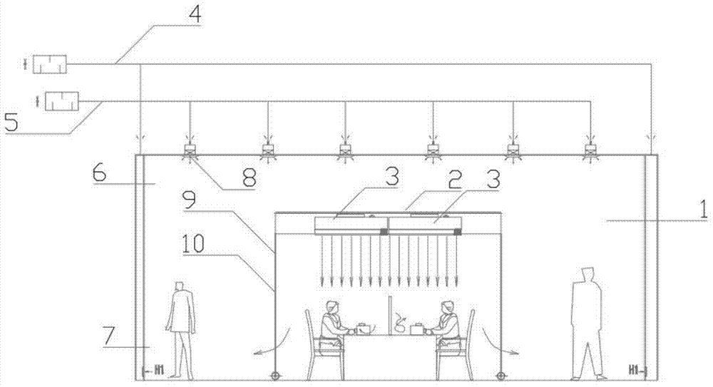
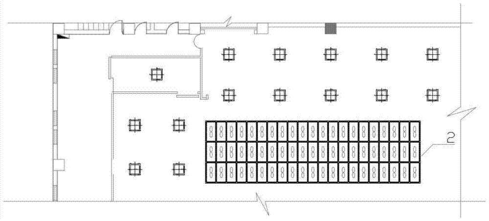

Image

  • A miniaturized 100-level laminar flow belt
  • A miniaturized 100-level laminar flow belt
  • A miniaturized 100-level laminar flow belt

Examples


Embodiment Construction

[0042] The present invention will be further described in detail below in conjunction with the accompanying drawings, so that those skilled in the art can implement it with reference to the description.

[0043] It should be understood that terms such as "having", "comprising" and "including" as used herein do not entail the presence or addition of one or more other elements or combinations thereof.

[0044] combine Figure 1 to Figure 3, there are some defects and drawbacks in the existing 100-level laminar flow zone, which are summarized as follows:

[0045] 1). In order to create a clean environment with relatively stable airflow and little interference, the 100-level laminar flow belt occupies a relatively large space: it is isolated from the surrounding space by dozens of FFUs through supporting frames and transparent enclosures. From a physical point of view, it can be regarded as a super-large equipment for the peripheral clean area. No matter where it is installed in...


PUM


Abstract

The invention discloses a miniaturized hundred-grade laminar flow zone, comprising a fan filter bank, a fan filter bank connecting base, a double air-out plenum chamber, and support columns. The fan filter bank is used to filter airflow absorbing from ten-thousand-grade or higher grade laminar flow spaces and blow the filtered airflow into the miniaturized hundred-grade laminar flow zone. The fan filter bank connecting base is used to support and fix the square frame of the fan filter bank. The double air-out plenum chamber is in a V-shaped three-dimensional hollow structure with an upper opening, and two inclined side surfaces forming the V shape are provided with a plurality of waist-type holes, so that the double air-out plenum chamber receives airflow blown from the fan filter bank from the upper opening and blows the airflow to a workbench which is out of the double air-out plenum chamber through the waist-type holes. Four edges of the upper opening are welded on the bottom of the fan filter bank connecting base. The support columns are used to support the fan filter bank connecting base. The four corners of the sealed base frame of the fan filter bank are welding with connecting blocks. One end of the support column is screwed with the sealed base frame of the fan filter bank through a screw hole on the connecting block. The other end of the support column is fixed on the workbench.

Description

technical field [0001] The invention relates to a clean laminar flow belt used in a clean room. More specifically, the present invention relates to a small and simplified 100-level laminar flow belt that is easy to install. Background technique [0002] In the prior art, the 100-level laminar flow device is installed in the laminar flow space of 10,000 or above. In order to create a clean environment with relatively stable airflow and little interference, the space surrounded by the 100-level laminar flow zone is relatively large. It is surrounded by support frames, transparent enclosures between the support frames and dozens of fan filter units set on the support frames. From a physical point of view, for the peripheral clean area, the 100-level laminar flow belt can be regarded as a super-large equipment. No matter where it is installed in the clean area, it will have a great influence on the airflow distribution and direction of the original clean environment. [0003]...

Claims


Application Information

Patent Timeline
Patent Type & Authority Patents(China)
IPC IPC(8): F24F1/00F24F13/28F24F13/32F24F13/06
CPCF24F1/0007F24F13/06F24F13/28F24F13/32
Inventor 耿佐力蒋乃军邴绍同王力
Owner JIANGSU SUZHOU PURIFICATION TECH
Learn More