A multi-channel optical splitting adapter for optical power testing in smart substations

An intelligent substation, optical power technology, applied in the field of optical fiber communication, can solve the problems of reducing work efficiency, increasing loss, bending, etc., to achieve the effect of reducing optical power loss, improving work efficiency, and accurate measurement results

Active Publication Date: 2018-06-12
STATE GRID SHANDONG ELECTRIC POWER +1
View PDF16 Cites 0 Cited by
  • Summary
  • Abstract
  • Description
  • Claims
  • Application Information

AI Technical Summary

Problems solved by technology

[0005] 1. Use pigtails with different fiber interface forms to test the optical power of various smart devices. Due to the different optical power losses of different pigtails, there will be different errors in the test results, which may eventually cause the test of the same smart substation. The results have errors in comparative analysis, and even produce wrong results
[0006] 2. Use pigtails of different fiber interface forms to test the optical power of various smart devices, resulting in frequent replacement of the pigtails between the optical power meter and the optical fiber connector during work, reducing work efficiency
[0007] 3. The optical power test is carried out by replacing the connecting pigtail. The test staff needs to carry at least 3 optical fibers, 3 optical fiber storage bags, and 7 optical fiber sanitary sheaths, and a group of 3 people is required for testing (one person for testing, one person for recording) , one person carries pigtails and other materials), which increases the testers and their workload, and needs to repeatedly plug and unplug the optical fiber interface at the end of the optical power meter, which seriously affects the service life of the optical power
[0008] 4. Maintenance personnel carry multiple pigtails with them, resulting in scattered storage of pigtails, common bending phenomenon, increased loss, affecting the accuracy of optical power testing, and reducing the comparability of measurement results

Method used


Image

  • A multi-channel optical splitting adapter for optical power testing in smart substations
  • A multi-channel optical splitting adapter for optical power testing in smart substations
  • A multi-channel optical splitting adapter for optical power testing in smart substations

Examples


Embodiment Construction

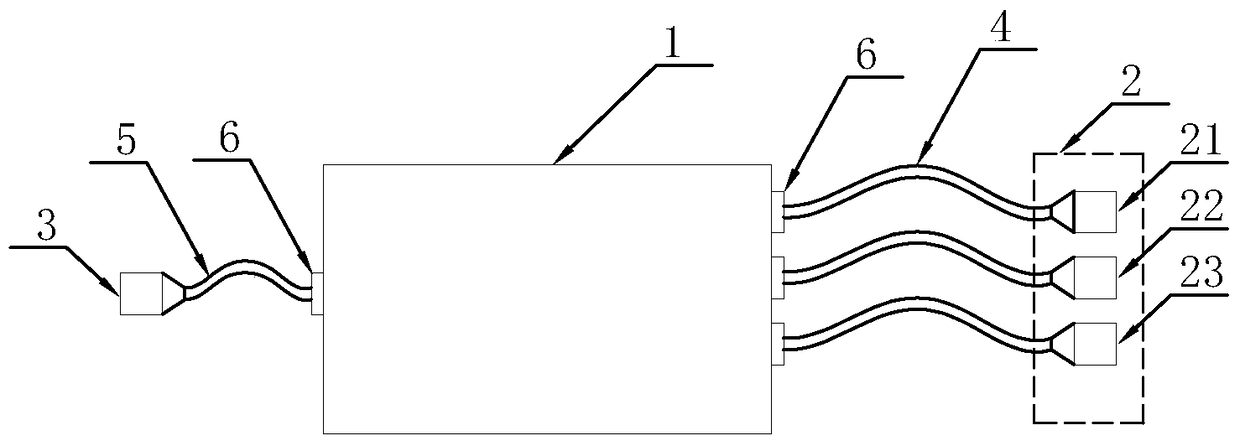
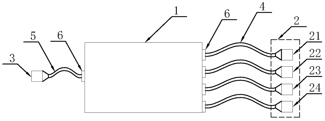
[0032]In order to clearly illustrate the technical features of this solution, the present invention will be described in detail below through specific implementation modes and in conjunction with the accompanying drawings. The following disclosure provides many different embodiments or examples for implementing different structures of the present invention. To simplify the disclosure of the present invention, components and arrangements of specific examples are described below. Furthermore, the present invention may repeat reference numerals and / or letters in different instances. This repetition is for the purpose of simplicity and clarity and does not in itself indicate a relationship between the various embodiments and / or arrangements discussed. It should be noted that components illustrated in the figures are not necessarily drawn to scale. Descriptions of well-known components and processing techniques and processes are omitted herein to avoid unnecessarily limiting the ...


PUM


Abstract

The invention discloses a multipath light splitting adapter for testing optical power for an intelligent transformer station. The multipath light splitting adapter includes a housing, a light splitting adapter circuit board, an input interface, an output interface, input fibers and an output fiber. The light splitting adapter circuit board is arranged in the housing. The housing is equipped with a plurality of wire inlet holes. One end of each input fiber passes through one wire inlet hole to be electrically connected to the light splitting adapter circuit board, and the other end of each input fiber is electrically connected to the input interface. One end of the output fiber passes through one wire inlet hole to be electrically connected to the light splitting adapter circuit board, and the other end of the output fiber is electrically connected to the output interface. The input interface includes multiple input interfaces with different types. The multiple input interfaces with different types are electrically connected to the light splitting adapter circuit board through the input fibers. The work efficiency of optical power testing is increased, and the accuracy of comparison and analysis of test results in the same intelligent transformer station is improved.

Description

technical field [0001] The invention relates to a device for testing optical power of an intelligent substation, in particular to a multi-channel splitting adapter for testing the optical power of an intelligent substation, which belongs to the technical field of optical fiber communication. Background technique [0002] Compared with conventional substations, smart substations have great changes in structure. Smart substations include substation layer equipment, bay layer equipment, process layer equipment, station control layer network and process layer network. The digital communication between the process layer and the bay layer of the smart substation replaces the electrical connection line of the secondary circuit of the traditional substation. The communication between the process layer, the bay layer and the station control layer and the communication between the layers are mostly replaced by optical fiber communication. Therefore, there are many optical fiber communi...

Claims


Application Information

Patent Timeline
Patent Type & Authority Patents(China)
IPC IPC(8): H04B10/07H04B10/25
Inventor 李静胡俊鹏王延安赵勇邵传军宋向前戎晓雪潘筱韩志宏
Owner STATE GRID SHANDONG ELECTRIC POWER
Why Eureka
Try Eureka