Eureka AIR delivers breakthrough ideas for toughest innovation challenges, trusted by R&D personnel around the world.

Flexible circuit board

A circuit board and circuit layer technology, applied in printed circuits, printed circuits, circuit thermal devices, etc., can solve problems such as troublesome, poor heat dissipation, and difficult installation, and achieve the effect of improving heat dissipation devices and good heat dissipation.

Active Publication Date: 2015-10-07
江西鑫力华数码科技有限公司
View PDF6 Cites 6 Cited by
  • Summary
  • Abstract
  • Description
  • Claims
  • Application Information

AI Technical Summary

Problems solved by technology

This kind of circuit board can be fixedly installed on the product by welding, but this kind of circuit board cannot be bent, and once bent, it will be basically damaged, so it cannot be installed against non-flat mounting surfaces, such as curved surfaces, stepped surfaces and other irregularities. regular mounting surface
There is also a flexible circuit board, which generally uses a PI soft base material layer as the base material layer, and then sets copper foil on the soft base material layer as the circuit layer, and then makes an insulating solder resist layer on the circuit layer. The circuit board can be bent to be attached to the surface of the product to be installed, but because it is a flexible material, it is troublesome to fix it on the surface of the product, and it is difficult to fix it by welding, and the substrate of this flexible circuit board The material is generally non-metallic, and the heat dissipation effect is relatively poor, especially for the flexible circuit board applied on the luminous lamp, the heat dissipation problem will be more prominent
Especially for the heat dissipation device of the car taillight, if the flexible circuit board is used, the heat dissipation is not good, and if the hard circuit board is used, it is not easy to install due to the curve of the car taillight

Method used


Image

  • Flexible circuit board
  • Flexible circuit board
  • Flexible circuit board

Examples


Embodiment

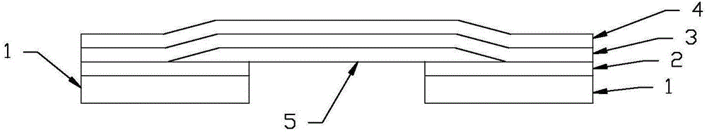
[0021] The second embodiment: if figure 2 As shown, the flexible circuit board is a single-layer circuit board, and the hard substrate 1 is at least two, figure 2 There are two pieces of the first flexible base material layer 5, and at least one piece of the first flexible base material layer 5, and the two sides of each first flexible base material layer 5 are connected to two hard substrates 1 respectively. That is, both sides are hard substrates, and the hard substrates are connected together through the first flexible substrate layer 5 .

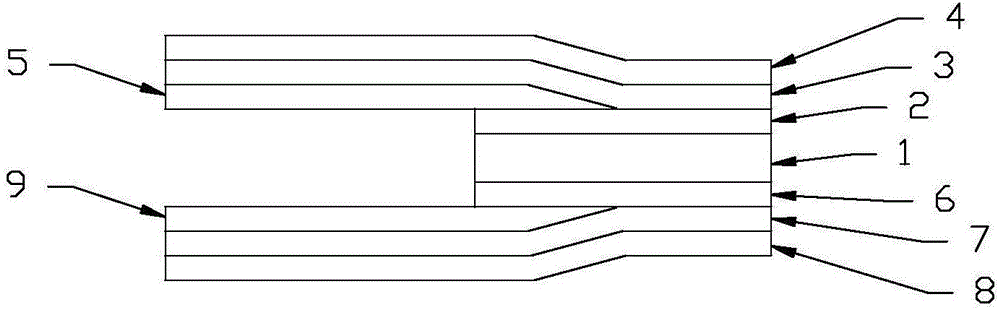
[0022] The flexible circuit board is a double-layer circuit board, and the hard substrate 1 is also provided with a second heat dissipation insulating adhesive layer 6, a second circuit layer 7 and a second insulating solder resist layer 8 in sequence. The flexible circuit board also includes a second flexible base material layer 9, the second circuit layer 7 extends from the second heat dissipation insulating adhesive layer 8 of the ...


PUM


Abstract

The invention provides a flexible circuit board. A part of the flexible circuit board adopts a hard base material, and includes a hard substrate, a first heat dissipating insulating adhesive layer is arranged on the hard substrate, a first circuit layer is arranged on the first heat dissipating insulating adhesive layer, a first insulating solder mask is arranged on the first circuit layer, the other part of the flexible circuit board adopts a flexible base material, and includes a first flexible base material layer, the first circuit layer extends from the first heat dissipating insulating adhesive layer of the hard substrate to an upper surface of the fixable base material layer, and a lower surface of a part of the flexible base material layer is connected with an upper surface of the hard substrate through the first heat dissipating insulating adhesive layer. In the flexible circuit board provided by the invention, the flexible base material and the hard base material are combined together, can be bent, and can be also applied to a circuit board that requires good heat dissipation, in mounting, welding can be performed directly on the hard substrate, which is simple and convenient, and an existing heat dissipation device of an automobile tail light can be improved.

Description

Technical field: [0001] The invention relates to the technical field of circuit board manufacturing, in particular to a flexible circuit board. Background technique: [0002] There are two types of circuit boards in the prior art. One is a hard circuit board, which generally uses an aluminum substrate, and then makes a circuit layer with copper foil on the aluminum substrate, and then makes an insulating solder resist layer on the circuit layer. This kind of circuit board can be fixedly installed on the product by welding, but this kind of circuit board cannot be bent, and once bent, it will be basically damaged, so it cannot be installed against non-flat mounting surfaces, such as curved surfaces, stepped surfaces and other irregularities. Regular mounting surface. There is also a flexible circuit board, which generally uses a PI soft base material layer as the base material layer, and then sets copper foil on the soft base material layer as the circuit layer, and then mak...

Claims


Application Information

Patent Timeline
Patent Type & Authority Applications(China)
IPC IPC(8): H05K1/02
CPCH05K1/0203H05K1/0298H05K2201/10106
Inventor 刘新华
Owner 江西鑫力华数码科技有限公司
Why Eureka
Eureka Blog
Learn More