Deburring apparatus with driving means for rotatably and reversibly driving the apparatus to and away of a billet
What is AI technical title?
AI technical title is built by PatSnap AI team. It summarizes the technical point description of the patent document.
A driving device and deburring technology, which is applied to auxiliary devices, milling machine equipment, welding equipment, etc., can solve the problems of hard-to-replace worn cutting devices and difficult-to-cut devices, and achieve the effect of reducing maintenance costs
Active Publication Date: 2015-10-07
PRIMETALS TECH AUSTRIA GMBH
View PDF7 Cites 6 Cited by
Summary
Abstract
Description
Claims
Application Information
AI Technical Summary
This helps you quickly interpret patents by identifying the three key elements:
Problems solved by technology
Method used
Benefits of technology
Problems solved by technology
[0013] - Difficult to replace worn cutting units due to size,
[0014] - Difficulty replacing worn cutting units due to inaccessibility of these parts
Method used
Image
Click on the blue label to locate the original text in one second.
Reading with bidirectional positioning of images and text.
Examples
Embodiment Construction
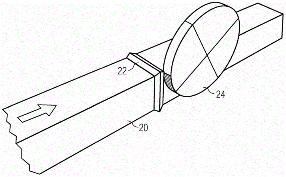
[0056] figure 1 It is a schematic diagram showing how the burr 20 existing on the welding position of two blanks is cut. The device according to the invention comprises an idler disk which is free to rotate about its axis when an appropriate torque is applied.
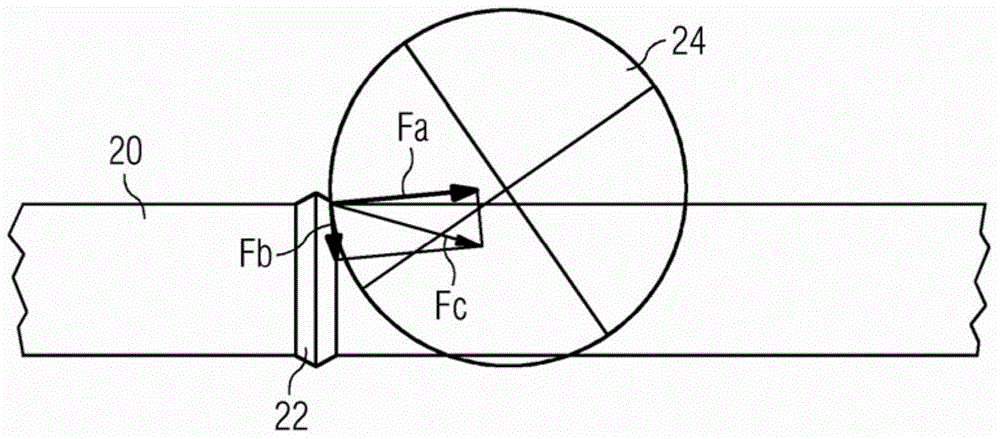
[0057] Such as figure 2As can be seen, the disc is positioned such that the reaction force experienced by the cutting disc when it contacts the burr causes the disc to rotate. Thus, no rotary drive mechanism (eg, a motor) is required for cutting. The reaction force Fc has a horizontal component Fa and a vertical component Fb. The cutting disc torque is the product of the vertical component Fb of the reaction force and the radius of the cutting disc.
[0058] Also, considering that each cutting disc is idling and only rotates when it contacts a burr, or that is, each cutting disc rotates at a speed that is a result of the stock speed, there is no need to adjust the stock speed to the cutting speed . This makes th...
PUM
Property
Measurement
Unit
diameter
aaaaa
aaaaa
Abstract
Apparatus (25, 25') for removing burrs (22) on billets (20) characterized in that it comprises: - a supporting element (26, 26'), - at least two arms (28, 30, 28', 30') extending from said supporting element (26,26'), - deburring means (24, 34, 24', 34') able to be driven in rotation by burrs (22) of billets (20), the deburring means (24,34,24',34') being supported by the arms (28,30,28',30'), - driving means (35) for driving rotatably and reversibly the apparatus (25,25') between a stand-by position wherein the apparatus (25,25') is spaced apart from the billet (20) to be deburred and a working position wherein the deburring means (24,34,24',34') are close to the billet (20) to be deburred and are able to contact a burr (22).
Description
technical field [0001] The invention relates to a device for deburring during continuous rolling in which billets are joined together by welding. Background technique [0002] In modern rolling mills, billets are welded together to be subsequently rolled. When the blanks are welded to each other by flash butt welding, welding burrs are formed at the weld location by the flash and pressure exerted thereon. Since the welding burr is relatively large, it becomes a defect in the subsequent rolling process performed thereafter. During the rolling of the welded billet, there is even a possibility that the rolled product is damaged at the location of the defect. [0003] Therefore, the welding burrs must be completely removed before billet rolling. [0004] Document EP 1 057 563 discloses a method and an apparatus for deburring welded blanks, in which a cutting device located near the surface to be cleaned is translated towards the surface in order to intercept the burrs and per...
Claims
Application Information
Patent Timeline
Application Date:The date an application was filed.
Publication Date:The date a patent or application was officially published.
First Publication Date:The earliest publication date of a patent with the same application number.
Issue Date:Publication date of the patent grant document.
PCT Entry Date:The Entry date of PCT National Phase.
Estimated Expiry Date:The statutory expiry date of a patent right according to the Patent Law, and it is the longest term of protection that the patent right can achieve without the termination of the patent right due to other reasons(Term extension factor has been taken into account ).
Invalid Date:Actual expiry date is based on effective date or publication date of legal transaction data of invalid patent.

