Polishing device, method for applying polishing pad, and method for replacing polishing pad

A technology for grinding devices and grinding pads, which is applied in the direction of grinding devices, grinding machine tools, grinding tools, etc., can solve problems such as deformation of grinding tables, and achieve the effects of easy replacement operation, labor-saving stripping operation, and high-precision replacement

Inactive Publication Date: 2015-10-07
EBARA CORP
View PDF11 Cites 10 Cited by
  • Summary
  • Abstract
  • Description
  • Claims
  • Application Information

AI Technical Summary

Problems solved by technology

[0014] In this regard, the grinding table can be formed of various materials, but when the grinding table is formed of a material with a low heat-resistant temperature such as resin, the grinding table may generate heat such as deformation due to the heat treatment for coating the fluororesin. damage

Method used


Image

  • Polishing device, method for applying polishing pad, and method for replacing polishing pad
  • Polishing device, method for applying polishing pad, and method for replacing polishing pad
  • Polishing device, method for applying polishing pad, and method for replacing polishing pad

Examples


no. 1 Embodiment approach

[0111] Next, a polishing device and a polishing pad replacement method according to a first embodiment of the present invention will be described with reference to the accompanying drawings. In the following embodiments, a CMP (Chemical Mechanical Polishing: Chemical Mechanical Polishing) polishing device will be described as an example, but it is not limited thereto.

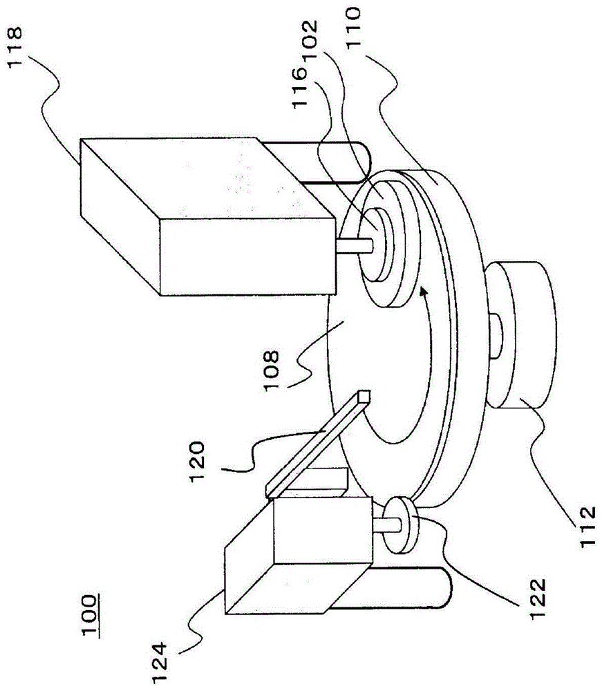
[0112] figure 1 It is a figure which schematically shows the whole structure of the polishing apparatus of 1st Embodiment. Such as figure 1 Shown, grinding device 100 has: grinding table 110, and the upper surface of this grinding table 110 can be installed the polishing pad 108 that is used for grinding substrate 102 such as semiconductor wafer; drive; a top ring 116 capable of holding the substrate 102 ; and a second motor 118 for rotationally driving the top ring 116 .

[0113] In addition, the polishing apparatus 100 has: a slurry line 120, which supplies the grinding fluid containing the abrasive materi...

no. 2 Embodiment approach

[0137] Next, a polishing device and a polishing pad replacement method according to a second embodiment of the present invention will be described with reference to the accompanying drawings. In the following embodiments, a CMP (Chemical Mechanical Polishing: Chemical Mechanical Polishing) polishing device will be described as an example, but it is not limited thereto. In addition, the polishing device and the polishing pad replacement method of the second embodiment may be implemented in combination with the polishing device and the polishing pad replacement method of the first embodiment described above.

[0138] Figure 4 It is a figure which schematically shows the whole structure of the polishing apparatus of 2nd Embodiment. Such as Figure 4 As shown, the grinding device 1100 has: a grinding table 1110, the upper surface of which can be installed with a grinding pad 1108 for grinding substrates 1102 such as semiconductor wafers; a first motor 1112, which rotates the gr...

no. 3 Embodiment approach

[0181] Figure 11 is a diagram schematically showing the overall structure of the polishing device. Such as Figure 11 As shown, the grinding device 2100 has: a grinding table 2110, the upper surface of which can be installed with a grinding pad 2108 for grinding substrates 2102 such as semiconductor wafers; a first motor 2112, which rotates the grinding table 2110 drive; the top ring 2116, the top ring 2116 can hold the substrate 2102; and the second motor 2118, the second motor 2118 rotates and drives the top ring 2116.

[0182] In addition, the polishing apparatus 2100 has: a slurry line 2120, which supplies a polishing slurry containing abrasive materials onto the upper surface of the polishing pad 2108; and a dressing tool unit 2124, which has 2108 Dressing tool disc 2122 for trimming (filing trimming).

[0183] In addition, the polishing device 2100 has: an operation panel 2130, which is used to input various operation commands and output various information about the...


PUM


Abstract

The work of replacing a polishing pad is easily performed, and thermal damage is prevented from occurring in a polishing table. A polishing apparatus 100 includes a polishing table 110 having an attachment surface 110a to which a polishing pad 108 used to polish a substrate 102 is attached. The polishing apparatus 100 also includes a silicone layer 111 provided on the attachment surface 110a of the polishing table 110 and interposed between the polishing table 110 and the polishing pad 108. By interposing the silicone layer 111, it is possible to easily detach and attach the polishing pad 108. In addition, since a heat treatment for coating the silicone layer 111 on the polishing table 110 is performed at a relatively low temperature, it is possible to prevent thermal damage from occurring in the polishing table 110 due to the heat treatment.

Description

technical field [0001] The invention relates to a grinding device, a method for attaching a grinding pad and a method for replacing the grinding pad. Background technique [0002] In recent years, polishing apparatuses have been used in order to polish the surface of substrates such as semiconductor wafers. The polishing apparatus rotates a polishing table to which a polishing pad for polishing the substrate is attached, and presses the substrate held by the top ring against the polishing pad to polish the surface of the substrate. [0003] In such a polishing apparatus, the polishing pad is used as a consumable item, and the polishing pad is periodically replaced. The replacement of the abrasive pad is generally performed by the operator's hands. [0004] In the attaching process of attaching the polishing pad to the grinding table, the operator manually attaches the polishing pad whose backside is an adhesive surface to the polishing table. The polishing pad is attached...

Claims


Application Information

Patent Timeline
Patent Type & Authority Applications(China)
IPC IPC(8): B24B37/20B24B37/12H01L21/304
CPCB24B37/34B24B37/04B24B45/006Y10T29/4973Y10T29/49826
Inventor 小菅隆一曾根忠一矶部壮一樱井武史平井英治滨浦薰小仓大
Owner EBARA CORP
Why Eureka
Try Eureka