C-shaped arm device, C-shaped arm retraining device and X-ray diagnosis device

A technology of holding device and C-arm, which is applied in the field of X-ray diagnostic device and C-arm device, can solve the problems of large rotation space, inconvenient operation and poor operation performance of C-arm device, and achieves small space and easy rotation. , the effect of improving the operation performance

Inactive Publication Date: 2015-10-14
TOSHIBA MEDICAL SYST CORP
View PDF6 Cites 3 Cited by
  • Summary
  • Abstract
  • Description
  • Claims
  • Application Information

AI Technical Summary

Problems solved by technology

[0006] However, when the operator performs this positioning, it is necessary to manually rotate the main bracket 200 and the C-arm as a whole, and the entire mass of the diagnostic device is applied to the bearings of the base, so a large force is required for rotation.
However, most of the medical staff who operate the device in the hospital are women, so the operation is not convenient, and the operation performance is especially poor for heavy equipment.
[0007] In addition, in the existing C-arm diagnostic devices, the center of rotation is located at the base, so that the rotation is at the bottom of the device, and the entire stand needs to be rotated during rotation, which requires a large rotation space

Method used


Image

  • C-shaped arm device, C-shaped arm retraining device and X-ray diagnosis device
  • C-shaped arm device, C-shaped arm retraining device and X-ray diagnosis device
  • C-shaped arm device, C-shaped arm retraining device and X-ray diagnosis device

Examples


no. 1 approach )

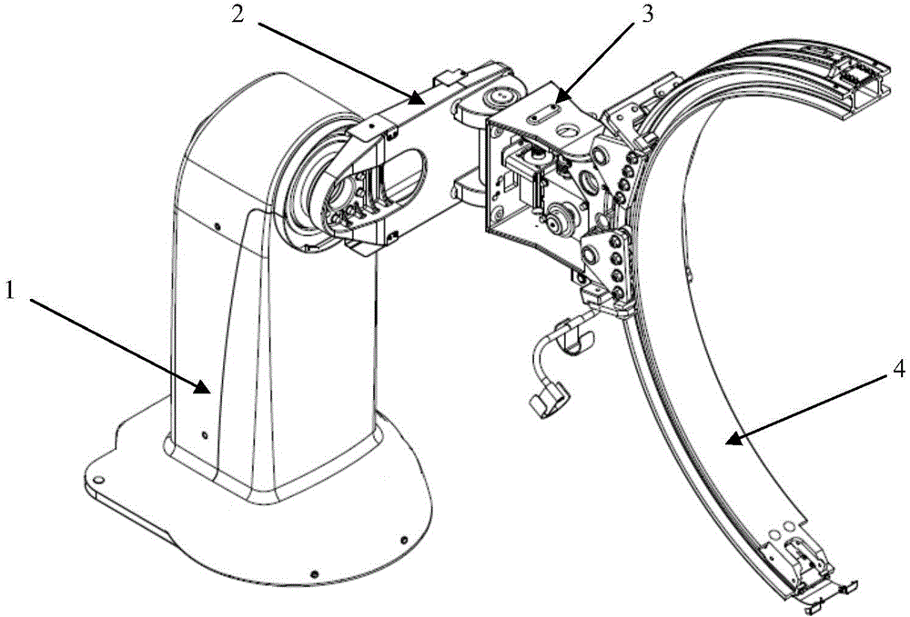
[0039] figure 2 is a schematic structural view of the overall structure of the C-arm device according to the first embodiment. Such as figure 2 As shown, the C-arm device generally has: a base 1 fixed to the ground, a cantilever bracket 2 with one end set on the base 1, the other end of the cantilever bracket 2 and connected with the cantilever bracket 2 so as to be able to rotate around the vertical axis. The C-arm holding part 3 rotates, and the C-arm holding part 3 is connected so as to be able to slide the C-arm 4 along the arc shape of the arm.

[0040] The internal structures of the base 1 , the cantilever bracket 2 , the C-arm holding part 3 and the C-arm 4 can follow the respective functional structures of the existing X-ray diagnostic apparatus, and the specific description is omitted. Here, only the connection relationship between the components will be described in detail.

[0041] exist figure 2 Among them, the base 1 is fixed to the ground, and the base 1 i...

no. 2 approach )

[0061] Figure 10 It is a schematic structural view of the overall structure of the C-arm device according to the second embodiment.

[0062] Such as Figure 10 As shown, the C-arm device generally has: a base 1 fixed to the ground and capable of rotating around a rotation axis, a cantilever bracket 2 with one end set on the base 1 , and the other end of the cantilever bracket 2 and connected to the cantilever bracket 2 A C-arm holding part 3 capable of rotating around a vertical axis, and a C-arm 4 connected to the C-arm holding part 3 so as to be able to slide along the arc shape of the arm.

[0063] Wherein, the base 1 has a turntable under the pillar, which can rotate around the vertical axis with the pillar as the center, thereby further enlarging the rotatable range. In addition, a mechanism for fixing the turntable may be used to lock the rotation of the base 1 when the rotation of the base 1 is not required.

[0064] The second embodiment differs from the first embo...


PUM


Abstract

The present invention proposes a C-type arm device which has improved operational and rotational performance, a relevant C-type arm holding device and an X-ray diagnostic device employing said C-type arm holding device. The inventive C-type arm device comprises a base, a cantilever bracket, a C-type arm holding part and a C-type arm. The cantilever bracket is provided on the base at one end. The C-type arm holding part is provided on the other end of the cantilever bracket and is connected to it in such a way that the part is rotatable about a vertical axis. Said C-type arm and said C-type arm holding part are connected to each other in such a way that the arm is slidable along a circular arc of itself.

Description

technical field [0001] The invention relates to a C-shaped arm device, a C-shaped arm holding device and an X-ray diagnostic device with the C-shaped arm holding device. Background technique [0002] Currently, medical equipment that uses a C-arm to diagnose patients on a bed is widely used. For example, medical image diagnostic equipment such as X-ray diagnostic equipment and MRI equipment have become important image diagnostic equipment along with the advancement of computer technology. [0003] Wherein, a typical C-arm device is a ground-fixed C-arm device in which a diagnostic device with a C-arm is fixed on the ground. [0004] Figure 13 A schematic structure of an existing ground-fixed C-arm device is shown. As shown in the figure, the existing C-arm device generally includes: a rotatable base 100 fixed on the ground, a main support 200 , and a C-arm 300 connected to the main support 200 and supported by the main support 200 . [0005] When using a C-arm like the il...

Claims


Application Information

Patent Timeline
Patent Type & Authority Applications(China)
IPC IPC(8): A61B6/00
CPCA61B6/4441A61B6/02
Inventor 刘文强
Owner TOSHIBA MEDICAL SYST CORP
Why Eureka
Try Eureka