Al technical title is built by PatSnap Al team. It summarizes the technical point description of the patent document.
A pressure vessel and rotating device technology, applied in auxiliary devices, auxiliary welding equipment, welding/cutting auxiliary equipment, etc., can solve the problem of inconvenient rotation control of pressure vessels, and achieve the effect of convenient and flexible control and convenient control.
Inactive Publication Date: 2015-10-14
ZHANGJIAGANG SHUNJIA INSULATION TECH
View PDF6 Cites 0 Cited by
Summary
Abstract
Description
Claims
Application Information
AI Technical Summary
This helps you quickly interpret patents by identifying the three key elements:
Problems solved by technology
Method used
Benefits of technology
Problems solved by technology
Existing pressure vessels are inconvenient to achieve rotation control
Method used
Image
Click on the blue label to locate the original text in one second.
Reading with bidirectional positioning of images and text.
Examples
Embodiment Construction
[0012] In order to make the technical means, creative features, goals and effects achieved by the present invention easy to understand, the present invention will be further described below in conjunction with specific embodiments.
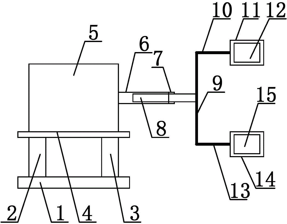
[0013] Such as figure 1 As shown, a pressure vessel rotation device includes a base 1, on which a first support foot 2 and a second support foot 3 are arranged, the first support foot 2 and the second support foot 3 have the same shape and size, and the first support foot The pin 2 and the second supporting pin 3 are vertically arranged, and a base plate 4 is provided between the ends of the first supporting pin 2 and the second supporting pin 3, and the base plate 4 is arranged horizontally, and the base plate 4 is provided with a drive motor 5 to drive The motor 5 is connected with a driving tube 6, and the driving tube 6 is arranged horizontally. The end of the driving tube 6 is provided with a coiled tube 7. The coiled tube 7 is connected with...
PUM
Abstract
The invention discloses a rotating device for pressure containers. The rotating device comprises a base, supporting legs are arranged on the base, a bottom plate is arranged between the ends of the supporting legs, a driving motor is arranged on the bottom plate and connected with a driving tube, a rotating tube is arranged at the end of the driving tube and connected with the driving tube through a buckle, a driving shaft is arranged inside the driving tube, a rotating rod is arranged at the end of the driving shaft and provided with connecting rods, and pressure containers are arranged at the ends of the connecting rods. The driving motor can conveniently control the rotating rod to rotate through the driving tube and the driving shaft, the rotating rod can control the pressure containers to rotate, rotation of the rotating tube can control the driving shaft to achieve horizontal adjustment along the driving tube, in this way, movement of the rotating rod is conveniently controlled, and rotation of the pressure containers is conveniently and flexibly controlled.
Description
technical field [0001] The invention relates to a rotating device, in particular to a pressure vessel rotating device. Background technique [0002] The manufacturing process of pressure vessels can generally be divided into: raw material acceptance process, scribing process, cutting process, rust removal process, machining (including planing, etc.) process, rolling process, assembly process, welding process (product welding test plate) , Non-destructive testing process, drilling and scribing process, general inspection process, heat treatment process, pressure test process, anti-corrosion process. Different welding methods have different welding processes. The welding process is mainly determined according to the material, grade, chemical composition of the workpiece to be welded, the structure type of the weldment, and the welding performance requirements. First of all, it is necessary to determine the welding method, such as manual arc welding, submerged arc welding, ar...
Claims
Application Information
Patent Timeline
Application Date:The date an application was filed.
Publication Date:The date a patent or application was officially published.
First Publication Date:The earliest publication date of a patent with the same application number.
Issue Date:Publication date of the patent grant document.
PCT Entry Date:The Entry date of PCT National Phase.
Estimated Expiry Date:The statutory expiry date of a patent right according to the Patent Law, and it is the longest term of protection that the patent right can achieve without the termination of the patent right due to other reasons(Term extension factor has been taken into account ).
Invalid Date:Actual expiry date is based on effective date or publication date of legal transaction data of invalid patent.