

Combined-type cable dome structure for elliptic plane with unequal-height boundary
A composite, cable dome technology, applied in the direction of roof, building components, building structure, etc., can solve the problems of reducing the mid-span deflection of the secondary structure and the small spanning capacity of the rigid roof, so as to reduce the cost and construction difficulty, and balance the cable. The effect of unbalanced force, reducing adverse effects
- Summary
- Abstract
- Description
- Claims
- Application Information
AI Technical Summary
Problems solved by technology
Method used
Image

Examples
Embodiment Construction
[0025] In order to further understand the invention content, characteristics and effects of the present invention, the following examples are given, and detailed descriptions are as follows in conjunction with the accompanying drawings:
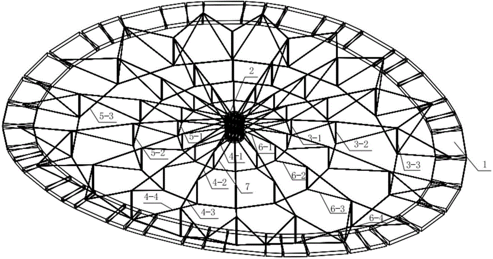
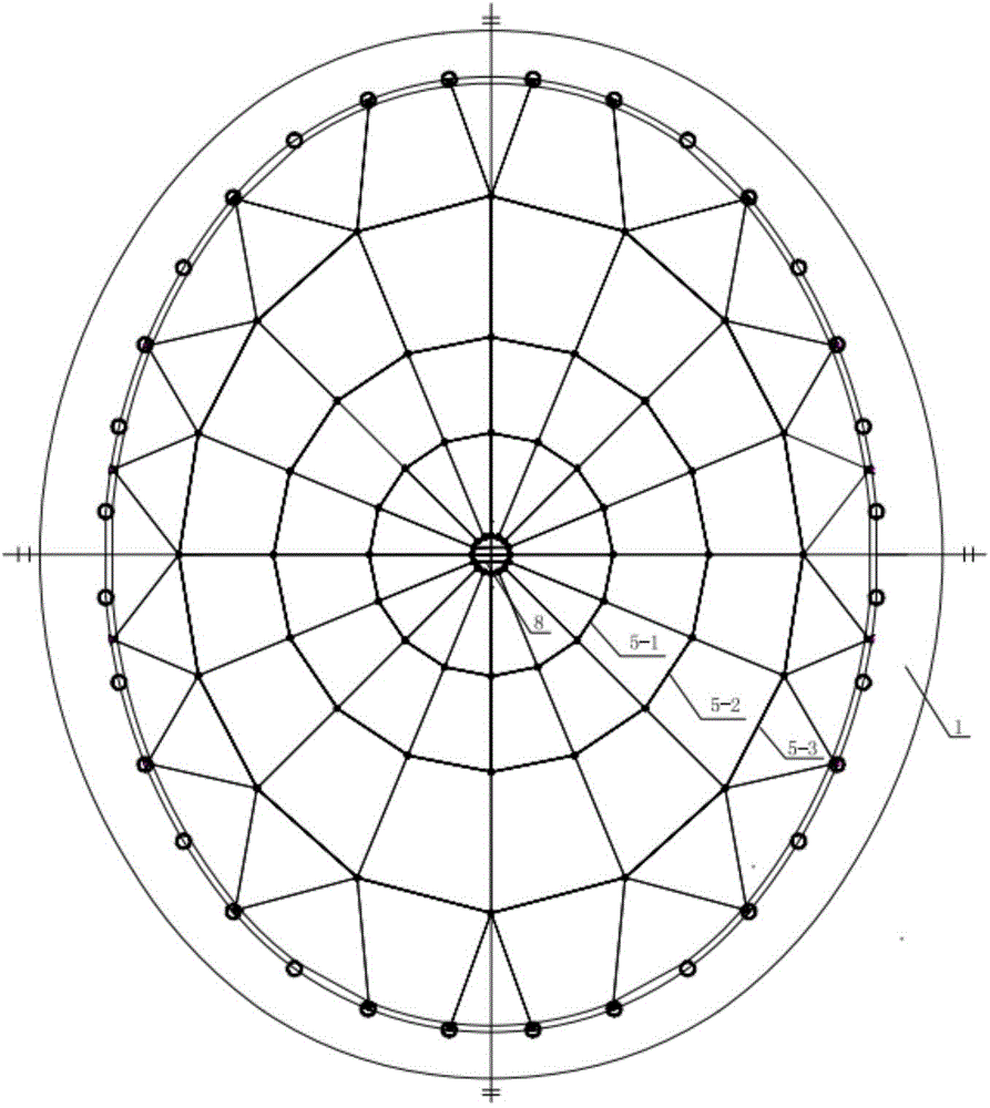
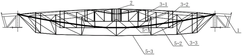
[0026] see Figure 1 to Figure 7 , an elliptical planar composite cable dome structure with unequal boundaries, including an outer ring beam 1 applied on the top of the lower structure column with different heights, and the outer ring beam 1 adopts a space curve that changes with the elevation of the lower structure column top Form, the horizontal projection of the outer ring beam 1 is an ellipse. The outer ring beam 1 can adopt concrete or steel structure. In this embodiment, the above-mentioned ellipse has a major axis of 102 m and a minor axis of 81 m, and the height of the column tops of the lower structure is not equal, and the difference between the lowest point of the major axis and the highest point of the short axis is 5.7 m.
[00...
PUM
 Abstract
Description
Claims
Application Information