Method for determining a crankshaft position of an internal combustion engine

A crankshaft position, internal combustion engine technology, applied in mechanical equipment, engine control, fuel injection control, etc., can solve the problems of uncertain working stroke, distinction, etc.

Inactive Publication Date: 2015-10-14
ROBERT BOSCH GMBH
View PDF9 Cites 11 Cited by
  • Summary
  • Abstract
  • Description
  • Claims
  • Application Information

AI Technical Summary

Problems solved by technology

In a four-stroke engine with one cylinder, the crankshaft makes two full revolutions per working cycle, so that the backlash can determine the crankshaft position but not the wor...

Method used


Image

  • Method for determining a crankshaft position of an internal combustion engine
  • Method for determining a crankshaft position of an internal combustion engine
  • Method for determining a crankshaft position of an internal combustion engine

Examples


Embodiment Construction

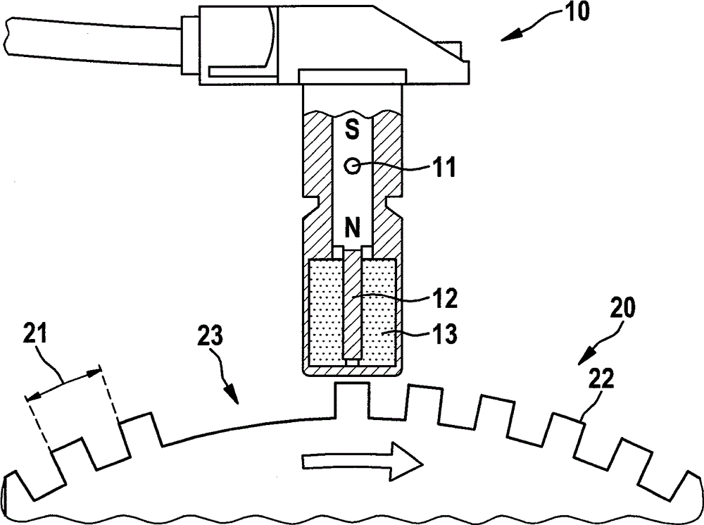
[0026] exist figure 1 A sensor wheel 20 and a corresponding inductive sensor 10 are schematically shown in FIG. 1 , which are used, for example, for determining the rotational speed in the prior art. The sensor wheel 20 is here generally fixedly connected to the crankshaft of the internal combustion engine, and the sensor 10 is fixedly mounted at a suitable location.

[0027] The sensor wheel 20 , usually made of ferromagnetic material, has teeth 22 which are arranged on the outside with a space 21 between them. At a position on the outside, the sensor wheel 20 has a gap 23 of the length of the specified number of teeth. This gap 23 serves as a reference mark for identifying the absolute position of the sensor wheel 20 .

[0028] The sensor 10 has a bar magnet 11 on which a soft-magnetic pole pin 12 is mounted. The pole pin 12 is in turn surrounded by an induction coil 13 . When the sensor wheel 20 rotates, the teeth 22 and the gap between every two teeth alternately pass ...


PUM


Abstract

The invention relates to a method for determining a crankshaft position of an internal combustion engine; a speed curve of the crankshaft is detected via a time; wherein the crankshaft position (OT *) is determined by comparing the speed characteristic with a known speed course of a working cycle of the internal combustion engine; wherein the known speed curve has a characteristic of the crankshaft position portion; wherein a signal of a crank shaft coupled to the electric machine is detected; wherein a least once per working cycle occurring value (OT 'OT' 'OT' '') of the signal is taken into account in determining the crankshaft position; and wherein determining the crankshaft position by superimposing and / or combining crankshaft position as determined by comparison of the speed curve is determined by the crankshaft position as from the value (OT 'OT' 'OT' '').

Description

technical field [0001] The invention relates to a method for determining the crankshaft position of an internal combustion engine. Background technique [0002] The operation of modern internal combustion engines requires information about the current engine speed to be available to the electronic engine controller. For this purpose, a sensor wheel mounted on the crankshaft of the internal combustion engine can be used, the rotational speed of which is detected, for example, by means of an inductively acting sensor or a Hall sensor. The sensor registers the passing metal markers and the rotational speed is determined from the time difference between the two markers. [0003] In order to implement the function of crankshaft angle synchronization, the absolute position of the crankshaft is also detected in order, for example, to correctly determine the timing of injection and, if applicable, ignition. This is achieved by the backlash at the sensor wheel, which is detected by...

Claims


Application Information

Patent Timeline
IPC IPC(8): F02D41/00
CPCF02D41/0097F02D41/0205
Inventor S.格罗德R.卡雷尔迈尔W.菲舍尔B.赖内克C.施坦布雷赫尔
Owner ROBERT BOSCH GMBH
Why Eureka
Try Eureka