
Ion implantation equipment

A technology of ion implantation equipment and ion emission, which is used in the manufacture of discharge tubes, electrical components, semiconductor/solid-state devices, etc., to achieve precise control and solve the control needs.

Inactive Publication Date: 2015-10-14
UNIV OF SCI & TECH OF CHINA
View PDF15 Cites 0 Cited by
  • Summary
  • Abstract
  • Description
  • Claims
  • Application Information

AI Technical Summary

Problems solved by technology

[0004] In view of this, the present application provides an ion implantation device for ion implantation of materials to solve the problem that existing ion implantation equipment cannot meet the need for higher precision control of implantation time

Method used


Image

  • Ion implantation equipment
  • Ion implantation equipment

Examples


Embodiment 1

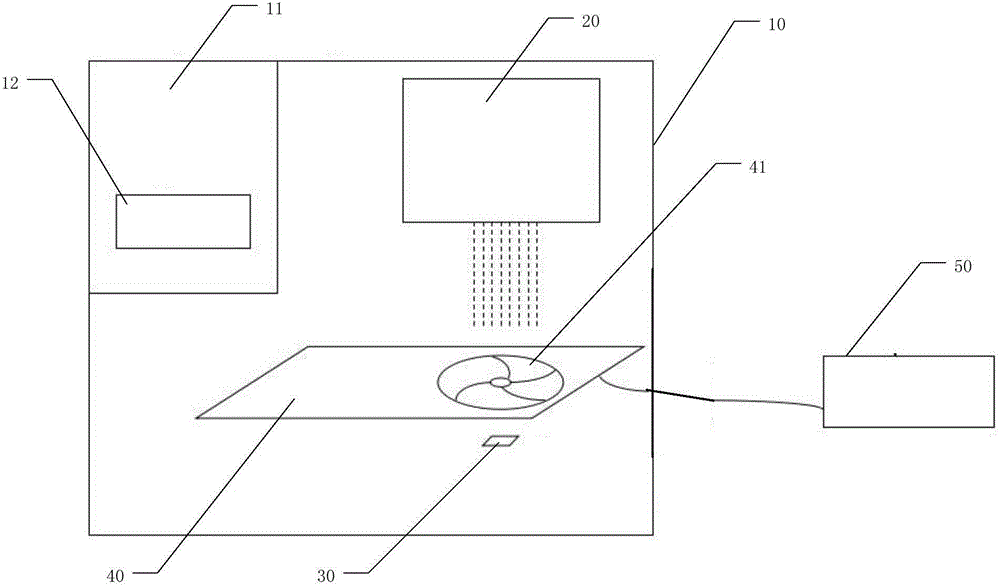
[0026] figure 1 It is a schematic diagram of an ion implantation device provided in an embodiment of the present application.

[0027] Such as figure 1 As shown, the ion implantation equipment provided in this embodiment includes a vacuum chamber 10 , an ion emitting device 20 , a target chamber 30 , a shutter device 40 and a shutter controller 50 . Wherein, the ion emitting device 20 , the target chamber 30 and the shutter device 40 are all arranged in the vacuum chamber 10 .

[0028] The vacuum chamber 10 provides a high-vacuum environment for ion implantation. Of course, in order to make the environment in the vacuum chamber reach a vacuum and a certain degree of vacuum, it is necessary to configure a corresponding vacuum device. Since almost all vacuum implantation equipment is equipped with this Vacuumizing device, so it is not repeated in the application.

[0029] The ion emitting device 20 is used to emit ion flow for implanting materials, and the ion emitting device...

Embodiment 2

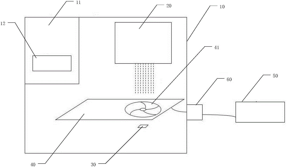
[0046] figure 2 It is a schematic diagram of an ion implantation device provided by another embodiment of the present application.

[0047] Such as figure 2 As shown, the ion implantation equipment provided in this embodiment has a sealing device 60 added on the basis of the previous embodiment.

[0048] Since the shutter device 40 is located in the vacuum chamber 10, and the shutter controller 50 is located outside the vacuum chamber 10, and the two need to be connected by wires to transmit corresponding control signals, in order to make the wires pass through the outer wall of the vacuum chamber 10 without As for affecting the sealing of the vacuum chamber 10 , the sealing device 60 allows the wires to pass through the outer wall of the vacuum chamber 10 to provide a safe and reliable sealing for the vacuum chamber 10 .

[0049] The sealing device 60 is preferably a flange device, and the flange device is fixed on the outer wall of the vacuum chamber 10 by bolts, so as t...


PUM


Abstract

The invention discloses ion implantation equipment which comprises a vacuum chamber and a shutter controller. The ion implantation equipment further comprises an ion emitting device, a target chamber and a shutter device; wherein the ion emitting device, the target chamber and the shutter device are arranged in the vacuum chamber. The ion emitting device is used for emitting an ion flow for performing ion implantation on a material in the target chamber. The shutter device is controlled by the shutter controller for being opened or closed, thereby controlling implantation amount of the ion flow. Because the corresponding speed of the shutter device can reach millisecond grade, more accurate control can be performed on the implantation time of the ion beam relative to the second-grade accuracy of traditional ion inputting equipment for performing controlling for starting and stopping, thereby settling a problem that existing ion implantation equipment cannot satisfy a requirement for higher-precision control for the implantation time.

Description

technical field [0001] The present application relates to the technical field of semiconductors, and more specifically, to an ion implantation device. Background technique [0002] Ion implantation is a material science that accelerates ions in an electric field and embeds them in another solid. It is widely used in the field of material modification engineering. This process can change the physical, chemical or electronic properties of solids. Ion implantation equipment for ion implantation of materials is mainly composed of ion sources, mass analyzers, accelerators and target chambers. Among them, the ion source is used to ionize the gaseous particles of the elements to be implanted into ions, and then screen out the required ions through the mass analyzer, accelerate the ions through the accelerator, and finally lead them to the target chamber and inject them on the material to be modified. . [0003] Traditional ion implantation equipment mainly utilizes the working pr...

Claims


Application Information

Patent Timeline
IPC IPC(8): H01J37/317H01L21/265
Inventor 刘钊希王鹏飞丁哲杜江峰石发展
Owner UNIV OF SCI & TECH OF CHINA
Learn More