A kind of slag accumulating cooling device and working method under the furnace

A cooling device and slag technology, applied in the manufacture of converters, etc., can solve the problems of wheels falling off the track, reducing equipment life, and rail thickening, so as to prevent adhesion on the rail, reduce equipment loss, and ensure smooth production line effect

Active Publication Date: 2021-12-21
SHANDONG IRON & STEEL CO LTD
View PDF7 Cites 0 Cited by
  • Summary
  • Abstract
  • Description
  • Claims
  • Application Information

AI Technical Summary

Problems solved by technology

Since the initial temperature of the accumulated slag is as high as 1000 degrees or more, it will cause certain damage to the surrounding key equipment such as rails, ladle car body, slag car body, slag retaining plate, etc., which reduces the life of the equipment, and seriously causes the equipment to deform and cannot be used. forced to replace
If there is a lot of liquid steel in the accumulated slag, it is easy to adhere to the steel equipment and is not easy to peel off. If the rail under the furnace is adhered by liquid steel, it is easy to form nodules on the rail, making the rail partially deformed. Coarse or even deformed, resulting in production accidents such as ladle trucks and slag truck wheels falling off the road, and the converter is forced to turn to the maintenance state, which will seriously affect the production progress, and the recovery time is generally more than 8 hours
When the rail under the furnace is seriously deformed due to adhesion and cannot be used, it is necessary to replace the rail, and the replacement time will be as long as 30 hours or more, which will have a great impact
[0003] In the prior art, there is no effective cooling method for molten slag falling into the track. Although water cooling is a common method in many fields, in the field of smelting, especially in the field of steelmaking, due to the particularity of the application environment, There is a great danger in using water to cool the track slag. In the prior art, it is forbidden to use water to cool down the high-temperature slag. When pouring the slag, it must not be poured in a wet or water-logged place to avoid the phenomenon of blasting (explosion). Therefore, there are many technical problems that need to be solved in cooling the slag with water, which limits the use of water to cool down the rail slag under the furnace.

Method used


Image

  • A kind of slag accumulating cooling device and working method under the furnace
  • A kind of slag accumulating cooling device and working method under the furnace
  • A kind of slag accumulating cooling device and working method under the furnace

Examples


Embodiment 1

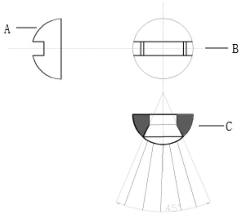
[0060] A kind of nozzle, described nozzle comprises a channel, and the cross-section of described channel is isosceles trapezoid, and the included angle of two waists of described trapezoid is 45 °, and the height of described channel is 2mm, and the upper base of described trapezoid The length is 10 mm, and the distance between the two bases of the trapezoid is 6 mm.

[0061] The end with a small opening at the end of the channel is a fluid inlet.

[0062] The channel fluid inlet is connected to a cylindrical channel structure.

[0063] The nozzle is made of metal copper.

[0064] The schematic diagram of the nozzle is shown in image 3

[0065] In the figure: A is a side schematic diagram, B is a front schematic diagram, and C is a cross-sectional schematic diagram

Embodiment 2

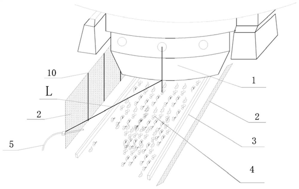
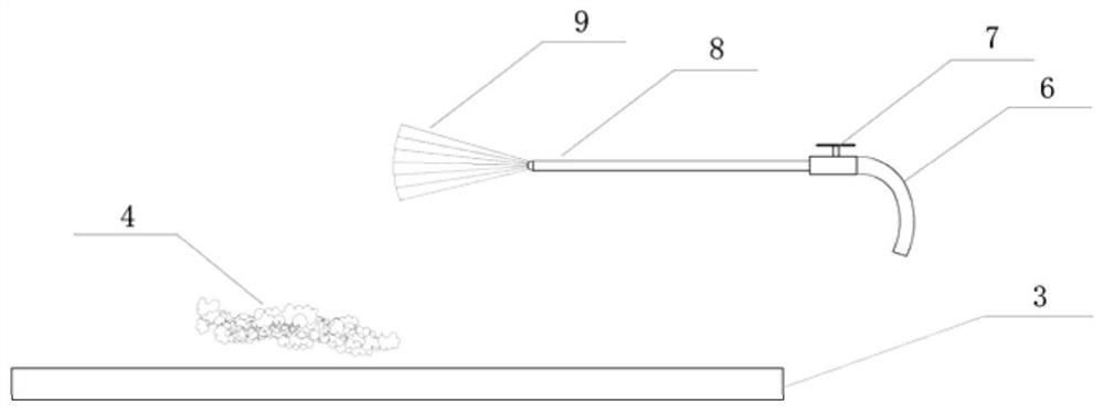
[0067] A slag cooling device, comprising a fire-retaining wall (2), a liquid spraying device (5), the liquid spraying device (5) comprising a liquid spraying rod (8), an infusion tube (6), and a control device (7), the The liquid spray rod (8) is arranged on the fire-retaining wall (2), on the rail (3) side of the fire-retaining wall (2), and the liquid outlet at the end of the rod body of the liquid spray rod (8) is provided with a In the nozzle, the liquid inlet at the end of the spray rod (8) is connected to the infusion tube (6), and the other end of the infusion tube (6) passes through the fire wall (2) and is connected to the liquid storage device; The height of the liquid spray rod (8) horizontally away from the track (3) is 1.5m, and a control device (7) is connected between the infusion pipe (6) and the liquid spray rod (8) to control the liquid pressure; see figure 1 , figure 2 .

[0068] The rod inner diameter of the liquid spray rod is Φ15mm.

[0069] The rod b...

Embodiment 3

[0074] A furnace body device equipped with the slag cooling device described in Embodiment 2, comprising: a fire-retaining wall (2), a liquid spray device (5), and a furnace body (1); the liquid spray device (5) includes a liquid spray rod (8), infusion tube (6), control device (7), the liquid spray rod (8) is arranged on the fire-retaining wall (2), and is arranged on the rail (3) side of the fire-retaining wall (2), the described The liquid outlet at the end of the rod body of the spray rod (8) is provided with the nozzle described in Embodiment 1, the liquid inlet at the end of the rod body of the liquid spray rod (8) is connected to the infusion tube (6), and the infusion tube (6) ) passes through the fire wall (2) and is connected with the liquid storage device; the height of the horizontal distance track (3) of the liquid spray rod (8) is 1.5m, between the infusion pipe (6) and the liquid spray rod (8 ) is connected with a control device (7), used to control the liquid p...


PUM

PropertyMeasurementUnit
heightaaaaaaaaaa
angleaaaaaaaaaa
heightaaaaaaaaaa

Abstract

The present invention relates to an under-furnace slag cooling device and working method, in particular to a nozzle and a slag cooling device, including a fire-retaining wall and a liquid spraying device; the liquid spraying device includes: a liquid spraying rod and an infusion tube; The liquid spray rod is arranged on the track side of the fire-retaining wall, the liquid inlet at the end of the rod body of the liquid-spray rod is connected with the infusion tube, and the other end of the infusion pipe passes through the fire-retaining wall and is connected with the liquid storage device, and the liquid spray rod The liquid outlet at the end of the rod body is provided with the nozzle. The present invention uses the above-mentioned device to reduce the temperature of the slag accumulated under the furnace, effectively preventing the molten slag from adhering to the track, avoiding the deformation of the track, and at the same time not generating Dangerous shooting phenomenon.

Description

technical field [0001] The invention relates to the field of converter steelmaking, in particular, the invention relates to an under-furnace slagging cooling device and a working method. Background technique [0002] The converter is a container for melting molten iron scrap steel into molten steel after a series of complex chemical changes through oxygen blowing. During the converter smelting process, a large amount of molten slag will be produced, and part of the molten slag will fall into the lower rail of the furnace to form slag accumulation. Since the initial temperature of the accumulated slag is as high as 1000 degrees or more, it will cause certain damage to the surrounding key equipment such as rails, ladle car body, slag car body, slag retaining plate, etc., which reduces the life of the equipment, and seriously causes the equipment to deform and cannot be used. forced to replace. If there is a lot of liquid steel in the accumulated slag, it is easy to adhere to...

Claims


Application Information

Patent Timeline
Patent Type & Authority Patents(China)
IPC IPC(8): C21C5/46
CPCC21C5/4646
Inventor 胡滨胡连军任科社杜金科
Owner SHANDONG IRON & STEEL CO LTD
Why Eureka
Try Eureka