Triboelectric nanometer generator capable of collecting liquid mechanical energy and power generating method thereof
A nanogenerator, a technology of mechanical energy, applied in triboelectric generators, nanotechnology for materials and surface science, nanotechnology, etc. Effect
- Summary
- Abstract
- Description
- Claims
- Application Information
AI Technical Summary
Problems solved by technology
Method used
Image
Examples
Embodiment 1
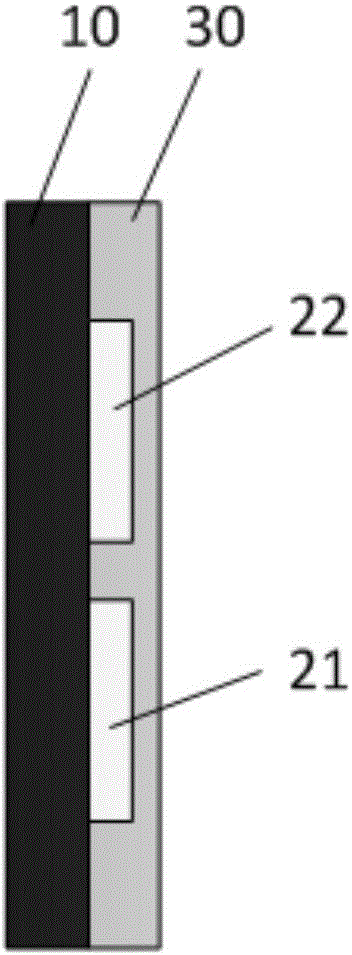
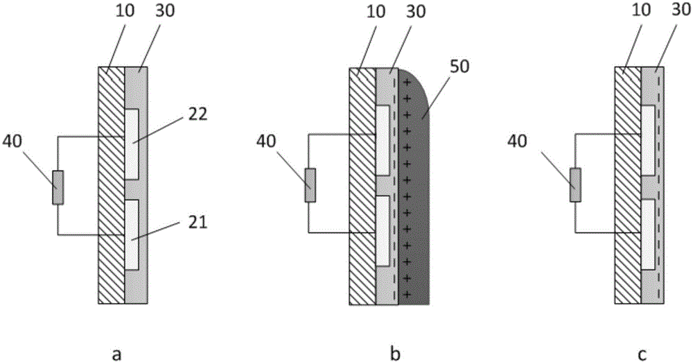
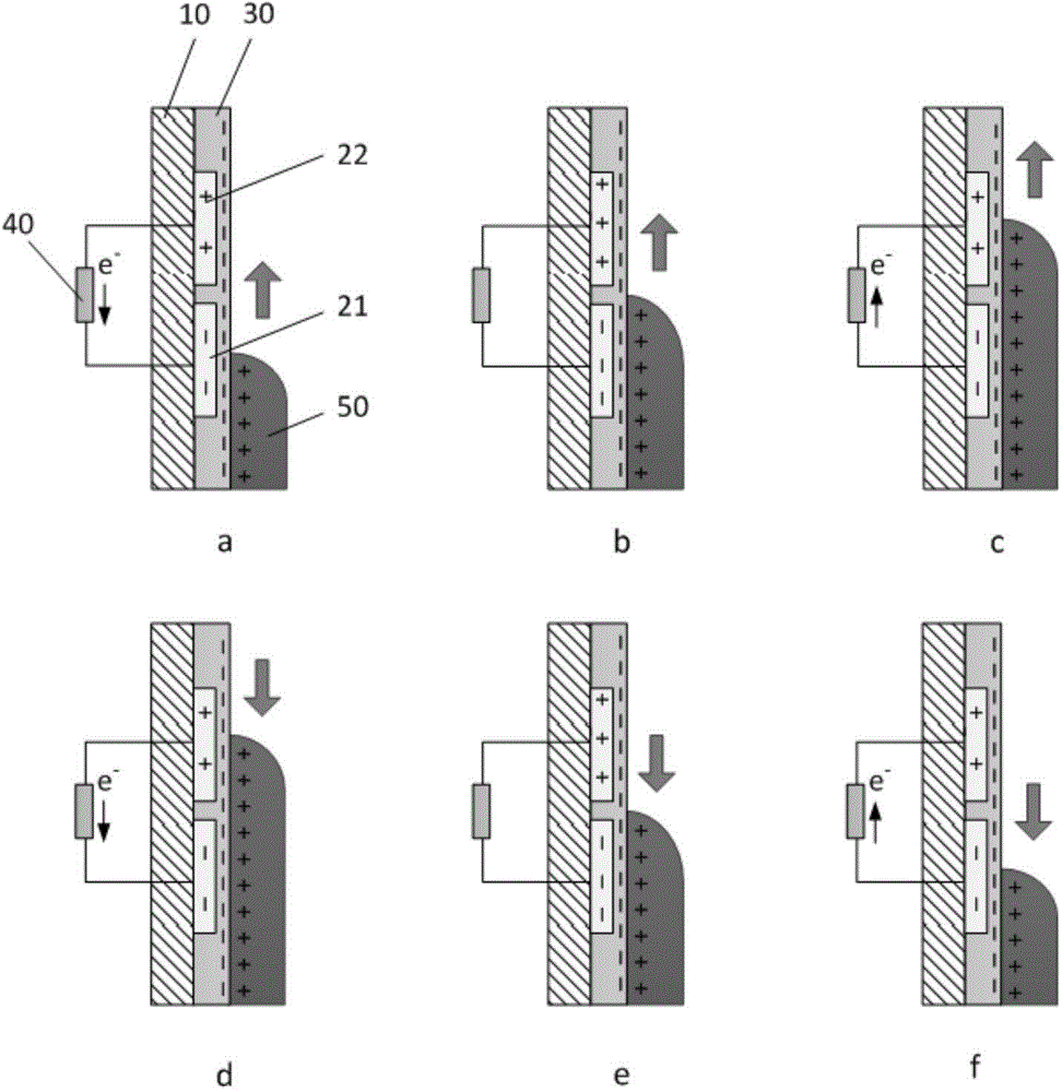
[0051] figure 1 It is a typical structure of the triboelectric nanogenerator of the present invention, including an insulating substrate 10 , power generation components and a friction layer 30 . Wherein, the power generation component is composed of a first electrode layer 21 and a second electrode layer 22, the first electrode layer 21 and the second electrode layer 22 are separately arranged on the substrate 10 and electrically connected to each other; the friction layer 30 covers the power generation The component is used to isolate the first electrode layer 21 and the second electrode layer 22 of the power generation component from the liquid environment in which the generator works. Fluctuation of the liquid rubs against the friction layer 30, causing the surface of the friction layer 30 to be charged; along with the fluctuation of the liquid, the charges on the surface of the friction layer 30 corresponding to the two electrode layers are successively shielded by the io...
Embodiment 2
[0079] In this embodiment, the two electrode layers of the power generation component are patterned electrode layers, Figure 5 As another typical structure of the generator in this embodiment, the first electrode layer 210 and the second electrode layer 220 in the conductive part are both of the slotting structure, and each electrode of the slotting structure is composed of several strip-shaped sub-electrodes parallel to each other. Arranged and connected to each other at one end to form. There is a gap 230 between the two pinion-shaped electrodes in a cross shape, such as Figure 5 As shown in , in the liquid wave direction indicated by the arrow, the strip-shaped sub-electrodes of the two electrodes are arranged alternately. The friction layer covers the power generation component, and isolates the first electrode layer 210 and the second electrode layer 220 of the power generation component from the liquid environment in which the generator works. In the liquid wave dire...
Embodiment 3
[0083] The generators in Embodiments 1 and 2 are suitable for environments such as sea wave fluctuations. When the liquid fluctuates, the change of the contact area with the generator is limited, and the efficiency of absorbing mechanical energy of flowing liquids such as rainwater is limited. In order to be suitable for the liquid environment of flowing water or raindrops, the generator provided in this embodiment includes a plurality of power generation components described in Embodiment 1 and the same number of rectification components, and the electrode layers of multiple power generation components The directions are arranged in parallel, and two adjacent power generation parts share one electrode layer, one power generation part outputs an electric signal and the other is rectified by the rectification part, and the output ends of all the rectification parts are connected in parallel as the output end of the generator. The structure of this embodiment is illustrated by ta...
PUM
 Abstract
Description
Claims
Application Information
 - R&D
- Intellectual Property
- Life Sciences
- Materials
- Tech Scout
- Unparalleled Data Quality
- Higher Quality Content
- 60% Fewer Hallucinations
Browse by: Latest US Patents, China's latest patents, Technical Efficacy Thesaurus, Application Domain, Technology Topic, Popular Technical Reports.
© 2025 PatSnap. All rights reserved.Legal|Privacy policy|Modern Slavery Act Transparency Statement|Sitemap|About US| Contact US: help@patsnap.com


