LED driver

An LED driver and signal technology, applied in lighting devices, light sources, output power conversion devices, etc., can solve the problems of high cost and large volume, and achieve the effect of constant current, good volume and long life.

Active Publication Date: 2015-10-14
INVENTRONICS HANGZHOU
View PDF6 Cites 1 Cited by
  • Summary
  • Abstract
  • Description
  • Claims
  • Application Information

AI Technical Summary

Problems solved by technology

[0005] In view of this, the present invention provides an LED driver to solve the problem of ensuring the filtering effect at the cost of large volume and high cost in the prior art

Method used


Image

  • LED driver
  • LED driver
  • LED driver

Examples


Embodiment Construction

[0024] The following will clearly and completely describe the technical solutions in the embodiments of the present invention with reference to the accompanying drawings in the embodiments of the present invention. Obviously, the described embodiments are only some, not all, embodiments of the present invention. Based on the embodiments of the present invention, all other embodiments obtained by persons of ordinary skill in the art without making creative efforts belong to the protection scope of the present invention.

[0025] The invention provides an LED driver to solve the problem in the prior art that a better filtering effect is achieved at the cost of large volume and high cost.

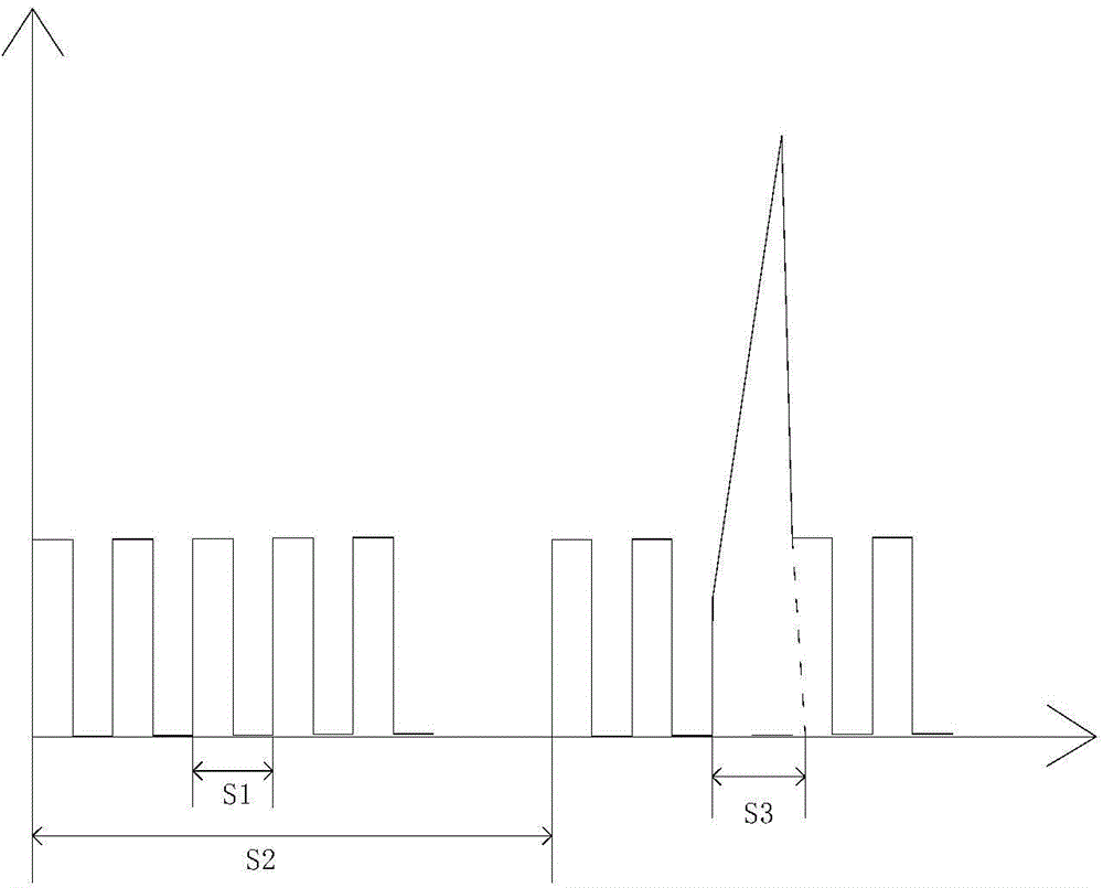
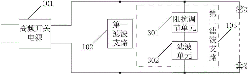
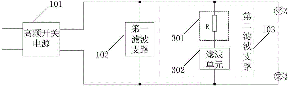
[0026] An LED driver such as figure 2 As shown, it includes: a high-frequency switching power supply 101 whose output end is connected to an LED load, a first filtering branch 102 and a second filtering branch 103 connected between the two output ends of the high-frequency switching power sup...


PUM


Abstract

The invention provides an LED driver. Different filter sub-circuits are allocated for various types of output signals, so that the output signals are filtered respectively. In this way, the device selecting and the parameter presetting for each filter sub-circuit can be conducted in the more targeted manner. Compared with a conventional LED driver provided with a single filter circuit in the prior art, the above LED driver is better in filtering effect on the premise that the factors of cost, size and service life are given consideration to at the same time. Therefore, the current for LED loads is kept constant. Meanwhile, the flicking/damaged condition of LED loads caused by the intermittent operation of a high-frequency switching power supply or the influence of dynamic pulse signals can be avoided.

Description

technical field [0001] The invention relates to the technical field of LED drivers, in particular to an LED driver. Background technique [0002] In the prior art, the filter circuit used at the output end of the LED driver is relatively simple, for example, an electrolytic capacitor is simply connected in parallel at the output end of the LED driver. Generally speaking, if the control method adopted by the LED driver is the frequency conversion control method, the lower the load power demand is, the higher the switching frequency is, see figure 1 , in addition to the switching frequency signal S1, the output signal of the LED driver may also be superimposed with the intermittent working frequency signal S2 and the dynamic pulse signal S3. The specific reason is that the LED driver is limited by the upper limit of the maximum frequency It will be in the low-frequency intermittent working mode. At this time, the output signal of the LED driver also includes the intermittent ...

Claims


Application Information

Patent Timeline
Patent Type & Authority Applications(China)
IPC IPC(8): H05B37/02H02M1/14
Inventor 葛良安俞杭冬
Owner INVENTRONICS HANGZHOU
Why Eureka
Try Eureka