Treatment instrument for endoscope, and endoscope system

A technology of endoscope and instrument, applied in the field of endoscope system

Active Publication Date: 2015-10-14
OLYMPUS CORP
View PDF10 Cites 6 Cited by
  • Summary
  • Abstract
  • Description
  • Claims
  • Application Information

AI Technical Summary

Problems solved by technology

[0007] In addition, when the bile duct has morphological characteristics, when there is stricture in the surrounding organs such as the duodenum, and when the patient has previously undergone surgery on the surrounding organs such as the duodenum, the duodenal The orientation of the bile duct near the nipple may be different from the 12 o'clock direction of the endoscopic view

Method used


Image

  • Treatment instrument for endoscope, and endoscope system
  • Treatment instrument for endoscope, and endoscope system
  • Treatment instrument for endoscope, and endoscope system

Examples


no. 1 Embodiment approach

[0055] Below, refer to Figure 1 to Figure 14 , the first embodiment of the endoscope system of the present invention will be described by taking the case where the endoscope treatment instrument is a nipplelotomy knife as an example.

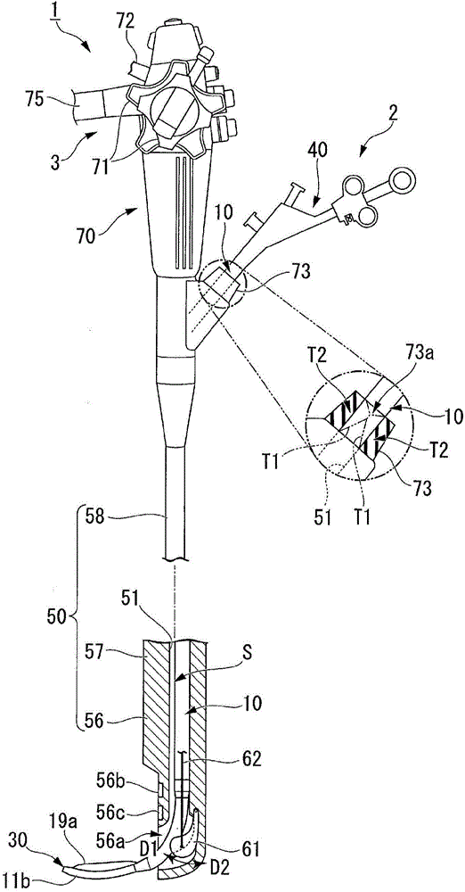
[0056] Such as figure 1 As shown, this endoscope system 1 has: a nippletome 2, which has a flexible insertion portion (sheath portion) 10; and an endoscope 3, which is formed with a channel through which the insertion portion 10 can be inserted. 51. That is, the papillotomy knife 2 is used in combination with the endoscope 3 .

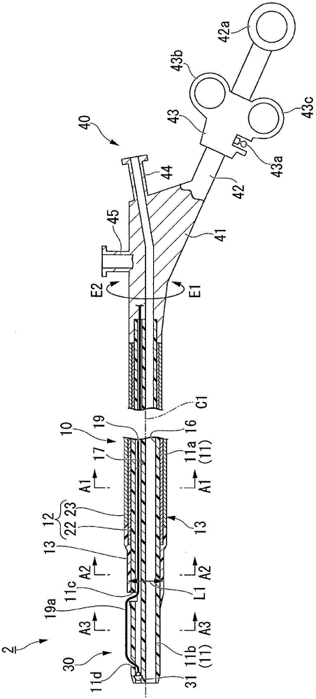
[0057] Such as figure 1 with figure 2 As shown, the nippletome 2 has the above-mentioned insertion part 10, a treatment part 30 provided on the front end side of the insertion part 10, and an operation part 40 provided at the proximal end of the insertion part 10 for operating the treatment part 30. .

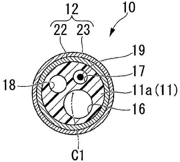
[0058] Insert part 10 such as Figure 2 to Figure 4 As shown, there are a sheath main body 11a constituting th...

no. 2 Embodiment approach

[0118] Next, refer to Figure 15 to Figure 26 The second embodiment of the present invention will be described, and the same reference numerals will be assigned to the same parts as those in the above-mentioned embodiment, and the description will be omitted, and only the different points will be described.

[0119] Such as Figure 15 to Figure 18 As shown, the nippletome 6 of this embodiment has an insertion part 90, a treatment part 110 provided at a position closer to the front end than the insertion part 90, and a treatment part 110 provided at the proximal end of the insertion part 90 for operating the treatment part. 110 of the operating unit 120 .

[0120] In this embodiment, for the insertion part 90 and the treatment part 110, use Figure 19 Multilumen tubing 91 is shown. exist Figure 19 In , the covering pipe 101 in the torque transmission member 95 described later is not shown.

[0121]The outer diameter of the proximal end side of the multi-lumen tube 91 is l...


PUM


Abstract

 The treatment instrument for an endoscope according to the present invention, used in combination with an endoscope having a raising base in a distal-end part of a channel, is provided with a flexible sheath part, a treatment part provided on a distal-end side relative to the sheath part, and an operating part for operating the treatment part, provided to a distal-end part of the sheath part. The sheath part has a sheath body in which a lumen extending along an axis line of the sheath part is formed, a held part held between the raised raising base and an internal peripheral surface of the channel when the sheath body is inserted in the channel, the held part being provided on a distal-end side of the sheath body, and a torque-transmitting member for transmitting a rotation torque inputted by a user on a proximal-end side and causing the sheath body to rotate about the axis line, the torque-transmitting member extending in the axis-line direction of the sheath part from a proximal-end side of the sheath body to the held part. The outside diameter of the held part is larger than the diameter of the largest inscribed circle in the portion of the raising base and the internal peripheral surface of the channel that holds the held part when the raising base is completely raised.

Description

technical field [0001] The present invention relates to an endoscope treatment instrument used in combination with an endoscope having a lifting base at a distal end portion of a channel, and an endoscope system including the endoscope treatment instrument. [0002] this application claims priority based on Japanese Patent Application No. 2013-135458 for which it applied to Japan on June 27, 2013, and uses the content here. Background technique [0003] When removing bile duct stones endoscopically, the duodenal papilla, which is the outlet of the bile duct, is narrow, so sometimes it is not possible to directly expel the stones. In this case, the papillary sphincter is incised using an endoscopic treatment instrument such as the Papillotome shown in Patent Documents 1 and 2, which passes through the endoscope, and the exit of the bile duct is enlarged to remove the stone. [0004] The position of the surrounding folds (はちまきfold) is approximately the same as the direction i...

Claims


Application Information

Patent Timeline
Patent Type & Authority Applications(China)
IPC IPC(8): A61B17/00
CPCA61B17/32056A61B1/00098A61B1/018A61B18/1492A61B19/5212A61B2017/00526A61B2017/00818A61B2017/2929A61B2018/00982A61B2018/141A61B2019/521A61B2090/309A61B90/361A61B17/3209A61B1/00087A61B17/320016A61B17/32002A61B2017/320032A61B17/32
Inventor 矢沼丰清川元
Owner OLYMPUS CORP
Why Eureka
Try Eureka