Gasification combustion system

A technology of combustion system and gasifier, which is applied in the direction of combustion type, gasification process, combustion method, etc.

Active Publication Date: 2015-10-14
COVANTA ENERGY CORPORATION
View PDF5 Cites 2 Cited by
  • Summary
  • Abstract
  • Description
  • Claims
  • Application Information

AI Technical Summary

Problems solved by technology

One of the problems associated with the conventional combustion of MSW and other solid fuels is that it produces sma

Method used


Image

  • Gasification combustion system
  • Gasification combustion system
  • Gasification combustion system

Examples


Embodiment Construction

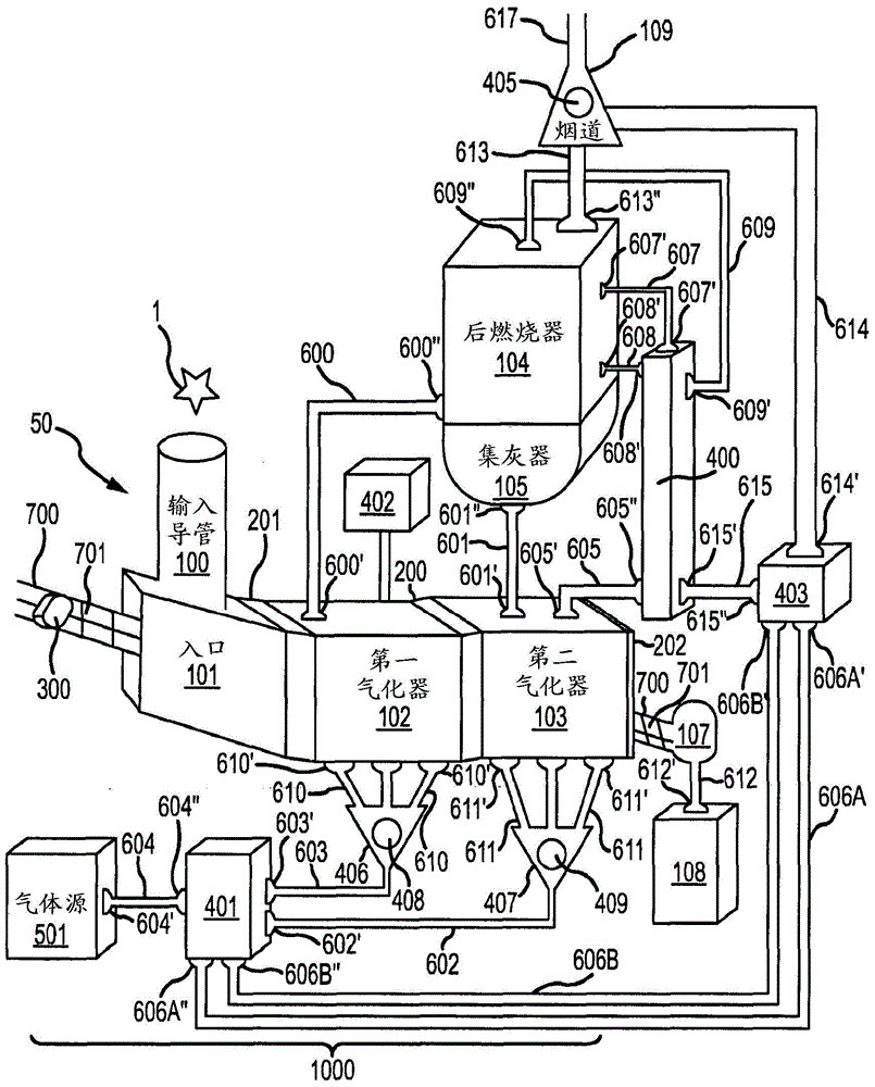
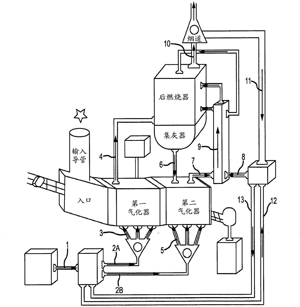
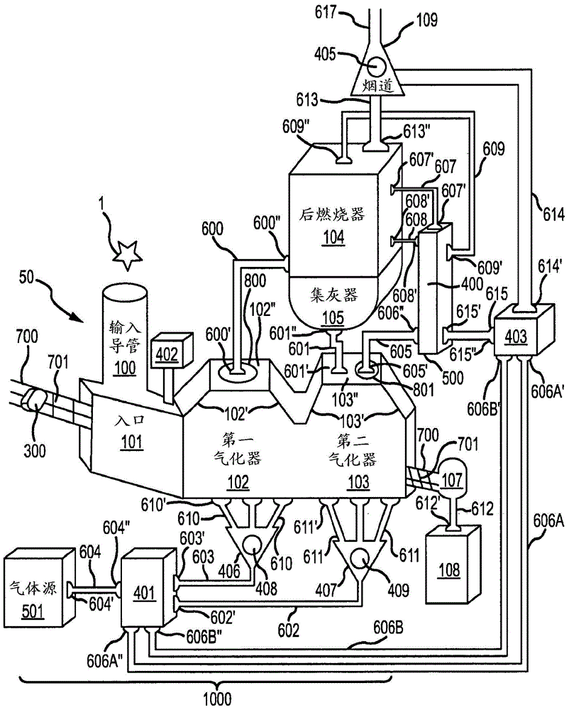
[0033] figure 1 One embodiment of the invention is shown. The combustion gasification system (broadly referred to as element 50 ) comprises an inlet 101 for receiving waste 1 , a first gasifier 102 , a second gasifier 103 and an afterburner 104 . Waste material 1 , garbage or waste can be placed in the inlet 101 through the input conduit 100 containing the housing. Inlet 101 may include an opening formed by the housing for receiving waste material. Processing of waste 1 typically starts in a first gasifier 102 . Processing may include one or more of the following functions: drying, devolatilization, gasification, or combustion. In some embodiments, oil or other combustible substances may be added to waste 1 to facilitate combustion.

[0034]Once the waste material 1 is inside the input 100 it can be pushed through the system 50 by the waste pusher 700 . The waste pusher 700 can take the form of a hydraulic cylinder 300 and a grate 701, such as figure 1 As shown, alternat...


PUM


Abstract

A two stage refuse gasification combustion system for processing refuse is disclosed. The system may contain features such as an advancer, a first and second gasifier, a gas regulator, and a post combustor. Additionally, methods for regulating gas and advancing refuse through a two stage refuse gasification combustion system are disclosed.

Description

[0001] Citation introduction [0002] This application claims priority to US Application No.: 13 / 725,110 filed December 21, 2012, which is hereby incorporated by reference in its entirety. technical field [0003] The present invention generally relates to gasification or combustion systems. More specifically, the present invention relates to methods and systems for regulating the flow of gases and waste through a gasifier or burner system. Background technique [0004] Municipal solid waste ("MSW") is the total product collected and disposed of by citizens and governments. MSW includes durable and nondurable goods, containers and packaging, food and yard waste, and a variety of inorganic waste from residential, commercial, and industrial sources. Examples include newsprint, electrical appliances, clothing, waste food, containers and packaging, disposable diapers, plastics of all types (including disposable tableware and foam) as part of an open list of single-use or dispo...

Claims


Application Information

Patent Timeline
IPC IPC(8): F23G5/027B09B3/00C10J3/00
CPCC10J3/002C10J3/721C10J3/723C10J2300/0909C10J2300/0946C10J2300/0956C10J2300/1606F23G5/027F23G5/165F23G2201/303
Inventor R·布罗各里奥张汉威R·贝克S·高夫
Owner COVANTA ENERGY CORPORATION
Why Eureka
Try Eureka