Glass fiber tensioning device applied to glass fiber spray painting robot

A technology of spraying robot and tensioning device, which is applied in the direction of spraying device, etc., and can solve problems such as glass fiber being wound on other equipment or the robot body and broken or pulled out from the glass fiber cutter, affecting the automatic spraying of the spraying robot, etc. , to achieve the effect of optimizing the spraying effect, high production capacity and smooth operation

Active Publication Date: 2015-10-21
SHANGHAI FANUC ROBOTICS
View PDF4 Cites 1 Cited by
  • Summary
  • Abstract
  • Description
  • Claims
  • Application Information

AI Technical Summary

Problems solved by technology

[0003] However, there are only existing spraying robots in the process of spraying glass fiber or other suitable materials. When the gun needs to be stopped to adjust the spraying posture or the workpiece is returned to the original point after spraying, the glass fiber cutter cuts the glass fiber at the spray gun. The glass fiber supplied by the follow-up feeding device continues to feed the wire to the spray gun due to inertia, which will easily cause the loose glass fiber to be wound on other equipment or the robot body, and the wire will be broken or pulled out of the glass fiber cutter, which will affect the automatic operation of the spraying robot. spraying

Method used


Image

  • Glass fiber tensioning device applied to glass fiber spray painting robot
  • Glass fiber tensioning device applied to glass fiber spray painting robot

Examples


Embodiment Construction

[0018] In order to make the technical means, creative features, goals and effects achieved by the present invention easy to understand, the following embodiments will specifically illustrate the fiberglass tensioning device provided by the present invention in conjunction with the accompanying drawings.

[0019] The glass fiber tensioning device provided in this embodiment is applied to a glass fiber spraying robot, and the glass fiber tensioning device is installed at the rotating shaft of the process arm of the spraying robot.

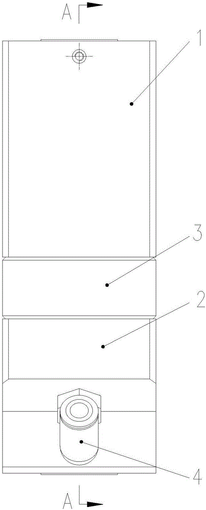
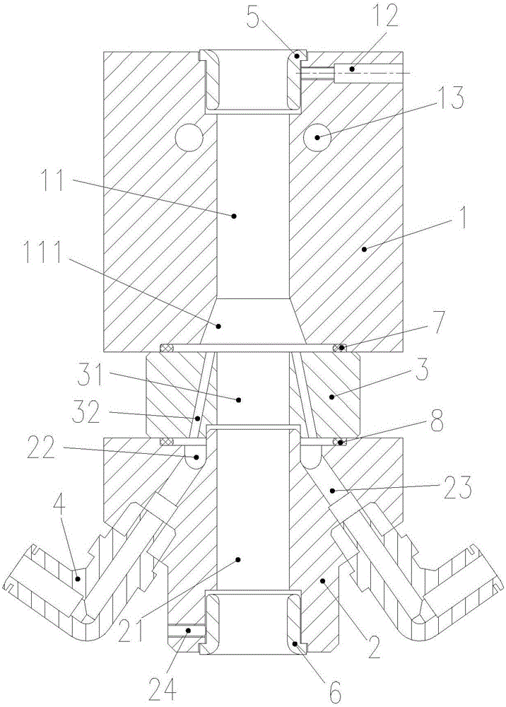
[0020] like figure 1 As shown, in this embodiment, the glass fiber tensioning device sequentially includes: a first tensioning body 1 , a second tensioning body 2 , and a flow guide block 3 along the conveying direction of the glass fiber. Among them, such as figure 2 As shown, the first tensioning body 1 has a first glass fiber channel 11, the second tensioning body 2 has a second glass fiber channel 21 aligned with the first glass fiber channel 1...


PUM


Abstract

The invention discloses a glass fiber tensioning device applied to a glass fiber spray painting robot. The glass fiber tensioning device comprises a first tensioning body, a second tensioning body and a flow guiding block, wherein the first tensioning body is provided with a first glass fiber channel, the second tensioning body is provided with a second glass fiber channel aligned to the first glass fiber channel, and the flow guiding block is located between the first tensioning body and the second tensioning body; a conical hole is formed on the end, facingthe flow guiding block, of the first glass fiber channel, an annular groove is formed in the end, facingthe flow guiding block, of the second tensioning body, and a plurality of flow guiding cavities communicating the conical hole with the annular groove are formed in the flow guiding block; a plurality of pneumatic connectors are installed on the outer side wall of the second tensioning body; a plurality of flow guiding holes are formed in the second tensioning body, and each flow guiding hole is communicated with the corresponding pneumatic connector and the corresponding annular groove. The glass fiber tensioning device can effectively solve the problem that glass fibers are loosened and thus wound around other equipment or a spray painting robot body and broken or pulled out of a glass fiber cutter.

Description

technical field [0001] The invention relates to spraying equipment, in particular to a glass fiber tensioning device applied to a glass fiber spraying robot. Background technique [0002] Spraying is a coating process widely used in production departments such as automobiles, instruments, electrical appliances, and enamel. However, due to the harsh environment of spraying operations (especially glass fiber spraying), it has a greater impact on the health of workers. Therefore, the traditional Manual spraying is gradually replaced by spraying robots, which are mainly composed of robot bodies, computers and corresponding control systems. The wrist of the more advanced painting robot adopts a flexible wrist, which can be bent in all directions and rotated. Its action is similar to that of a human wrist, and it can easily penetrate into the interior of the workpiece through a small hole to spray its inner surface, which has high spraying efficiency. High, good spraying effect a...

Claims


Application Information

Patent Timeline
Patent Type & Authority Applications(China)
IPC IPC(8): B05B13/02B05B15/00
CPCB05B13/02B05B13/0207B05B15/00
Inventor 徐文君董德权袁华雷沈为召顾玉兴陈竞新
Owner SHANGHAI FANUC ROBOTICS
Why Eureka
Try Eureka