Clamping structure for circuit board welding

A clamping structure and circuit board technology, applied in the directions of printed circuits, auxiliary devices, welding equipment, etc., can solve the problems of increasing the circuit board process, increasing the work intensity of the operator, reducing the welding efficiency of the circuit board, etc., to improve the clamping effect. , the effect of moving up to stabilize and improve accuracy

Inactive Publication Date: 2015-10-21
SICHUAN LANXUNBAOER ELECTRONICS TECH
View PDF12 Cites 7 Cited by
  • Summary
  • Abstract
  • Description
  • Claims
  • Application Information

AI Technical Summary

Problems solved by technology

[0002] In the prior art, the circuit board needs to be welded accurately and firmly when welding the electrical components, so it needs to be carried out in an environment with a uniform light source. At the same time, since the circuit board needs to weld multiple electrical components, that is The circuit board needs to be fixed before welding. The usual method is to use the press

Method used


Image

  • Clamping structure for circuit board welding

Examples


Example Embodiment

[0017] Example 1

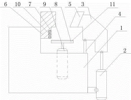
[0018] Such as figure 1 As shown, this embodiment includes a welding frame 1 and a hydraulic cylinder 2 fixed on the side wall of the welding frame 1. A baffle 6, a support rod 4, and a cylinder 9 are fixed on the welding frame 1. The output end of the hydraulic cylinder 2 is The movable block 3 is hinged, and the top end of the support rod 4 is hinged to the bottom surface of the movable block 3. A chuck 5 facing the baffle 6 is fixed on the side wall of the movable block 3, and the output end of the cylinder 9 A top plate 8 is fixed on the top plate, the baffle 6 is L-shaped, and the vertical part of the baffle 6 is fixed on the welding frame 1, the horizontal part of the baffle 6 is facing the chuck 5, and the baffle 6 is On the side wall of the vertical part of 6 close to the chuck 5, a rectangular groove 7 with an open end is opened, and a plurality of rollers 10 parallel to the top plate 8 are rotatably arranged in the rectangular groove 7. The side end...


PUM


Abstract

The invention discloses a clamping structure for circuit board welding. The clamping structure comprises a weld holder and a hydraulic cylinder, wherein a baffle, a supporting rod and an air cylinder are fixed to the weld holder, a movable block is hinged to the output end of the hydraulic cylinder, and the top end of the supporting rod is hinged to the bottom surface of the movable block; a chuck is fixed to the side wall of the movable block, a top plate is fixed to the output end of the air cylinder, and a rectangular groove is formed in the vertical portion of the baffle; a plurality of rollers parallel to the top plate are arranged in the rectangular groove in a rotary mode, the end of one side of the top plate is aligned with the outer wall of each roller in the vertical direction, and an elastic rubber mat is installed on the upper surface of the top plate. In the whole circuit board welding process, lifting and fastening of a circuit board are achieved by controlling the air cylinder and the hydraulic cylinder, movement of the circuit board during welding can be avoided through a U-shaped clamping area formed by the chuck, the top plate and the baffle, and then the welding precision of components on the circuit board is improved.

Description

technical field [0001] The invention relates to the field of welding of electronic components, in particular to a circuit board welding and clamping structure. Background technique [0002] In the prior art, the circuit board needs to be welded accurately and firmly when welding the electrical components, so it needs to be carried out in an environment with a uniform light source. At the same time, since the circuit board needs to weld multiple electrical components, that is The circuit board needs to be fixed before welding. The usual method is to use the pressure plate and bolts to fix the circuit board, and then perform welding. Further, in order to improve the stability of the welding, the circuit board is usually fixed at multiple points, increasing the The process of the circuit board before and after welding greatly reduces the welding efficiency of the circuit board, and at the same time increases the work intensity of the operator. Contents of the invention [00...

Claims


Application Information

Patent Timeline
IPC IPC(8): B23K37/04
CPCB23K37/0443B23K2101/42
Inventor 李胜峰
Owner SICHUAN LANXUNBAOER ELECTRONICS TECH
Why Eureka
Try Eureka