Feeding device of converter rotating chute

A technology of feeding device and chute, which is applied in the direction of manufacturing converters, etc., can solve the problems of inability to rotate the rotating cylinder, increase production and use costs, and difficulty in rotating the rotating cylinder, so as to reduce labor intensity of workers, improve work efficiency, and improve airtightness. Good results

Active Publication Date: 2015-10-21
JIANGSU YONGGANG GROUP CO LTD
View PDF4 Cites 6 Cited by
  • Summary
  • Abstract
  • Description
  • Claims
  • Application Information

AI Technical Summary

Problems solved by technology

The disadvantage of the above-mentioned converter rotary chute feeding device is that there will be a gap of about 10 cm between the inner fixed cylinder and the rotating cylinder, and a large amount of dust raised during the process of adding the alloy to the converter will enter the rotating cylinder and the outer cylinder through this gap. Between the fixed cylinders, the dust can easily jam the supporting rollers, making it difficult to rotate the rotating cylinder, and even impossible to rotate the rotating cylinder in severe cases. Therefore, workers must regularly clean the inside of the converter rotary chute feeding device, which not only increases Reduced the labor intensity of workers, and greatly increased the cost of production and use of enterprises

Method used


Image

  • Feeding device of converter rotating chute
  • Feeding device of converter rotating chute
  • Feeding device of converter rotating chute

Examples


Embodiment Construction

[0016] The present invention will be further described below in conjunction with the accompanying drawings and specific embodiments.

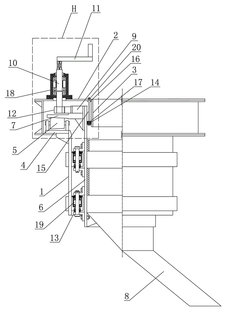
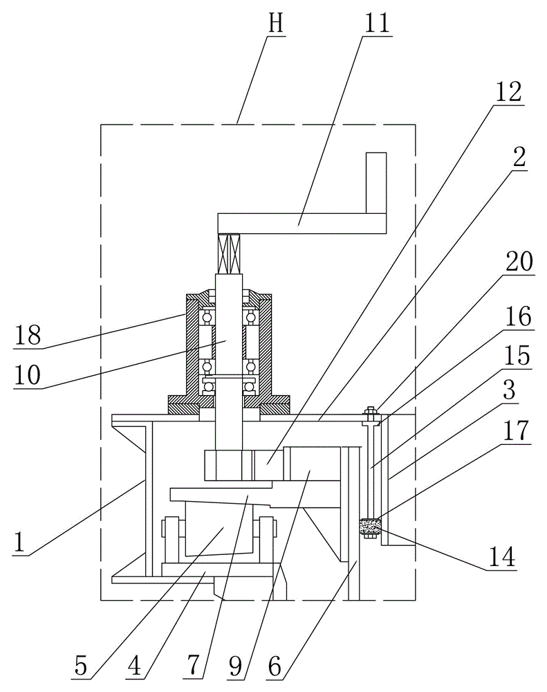
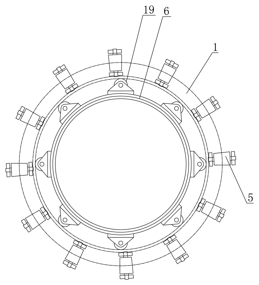
[0017] Such as figure 1 , figure 2 , image 3 As shown, the described converter rotary chute feeding device includes: an external fixed cylinder 1, a mounting plate 2 is arranged on the top cover of the external fixed cylinder 1, a feeding port is arranged at the center of the mounting plate 2, and at the feeding port The mounting plate 2 is provided with an inner fixing cylinder 3 sleeved in the outer fixing cylinder 1, an annular fixing seat 4 is arranged on the inner wall of the outer fixing cylinder 1, and on the annular fixing seat 4 along the outer fixing cylinder 1 A number of support rollers 5 are distributed at intervals in the circumferential direction, and the end faces of all the support rollers 5 jointly form a support platform. A rotating cylinder 6 is sleeved between the outer fixed cylinder 1 and the inner fixed cylinder 3. ...


PUM


Abstract

The invention discloses a feeding device of a converter rotating chute. The feeding device comprises an outer fixing cylinder with the top provided with an installation plate. A feeding port of the center of the installation plate is provided with an inner fixing cylinder, and an annular fixing seat is arranged on the inner wall of the outer fixing cylinder. The annular fixing seat is provided with a plurality of supporting rollers, and a supporting platform is formed by the supporting rollers. A rotating cylinder is arranged between the outer fixing cylinder and the inner fixing cylinder in a sleeved mode. The outer wall of the rotating cylinder is provided with an annular protruding shoulder, the bottom of the rotating cylinder is provided with the rotating chute, and the rotating cylinder is arranged on the supporting platform through the annular protruding shoulder of the rotating cylinder to be supported in the outer fixing cylinder. The bottom gap of the rotating cylinder and the outer fixing cylinder is sealed through an annular sealing plate. The outer wall of the rotating cylinder is provided with a gear ring, the installation plate is provided with a rotating shaft, the upper end of the rotating shaft is provided with a handle, the lower end of the rotating shaft is provided with a transmission gear meshed with the gear ring, and an annular high-temperature-resistance sealing piece is arranged between the rotating cylinder and the inner fixing cylinder. The annular high-temperature-resistance sealing piece is sealed and fixed between the rotating cylinder and the inner fixing cylinder through a detachable fixing mechanism. The feeding device has the advantage of being good in sealing performance.

Description

technical field [0001] The invention relates to a converter rotating chute feeding device for alloy feeding in a converter. Background technique [0002] At present, the alloys required in the converter steelmaking process are fed into the converter through the converter rotary chute feeding device. The structure of the currently used converter rotary chute feeding device is as follows: it includes an external fixed cylinder, a mounting plate is provided on the top cover of the external fixed cylinder, a feeding port is provided at the center of the mounting plate, and a feeding port is installed on the mounting plate at the feeding port. There is an inner fixed cylinder sheathed in the outer fixed cylinder, and an annular fixed seat is arranged on the inner wall of the outer fixed cylinder, and a number of supporting rollers are distributed along the circumferential direction of the outer fixed cylindrical body on the annular fixed seat. The end faces of the rollers toget...

Claims


Application Information

Patent Timeline
Patent Type & Authority Applications(China)
IPC IPC(8): C21C5/46
Inventor 张现瑞董志龙陈方圆燕全林张金波
Owner JIANGSU YONGGANG GROUP CO LTD
Why Eureka
Try Eureka