
Electric equipment protection guardrail

A technology for power equipment and protective fences, applied in the field of power equipment protective fences, can solve the problems of inability to monitor the operating status of power equipment, poor flexibility in placing and dismantling, and occupying a large space, so as to achieve improved isolation reliability, simple structure, The effect of strong site adaptability

Inactive Publication Date: 2015-10-21
WUJIANG SANDA HARDWARE TOOL FACTORY
View PDF3 Cites 0 Cited by
  • Summary
  • Abstract
  • Description
  • Claims
  • Application Information

AI Technical Summary

Problems solved by technology

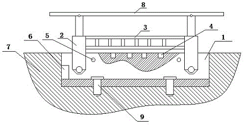
[0002] At present, in the management of some large-scale or high-voltage and ultra-high-voltage equipment, in order to improve the safety of equipment operation and provide effective reminders to operators, it is often necessary to isolate such power equipment with protective guardrails. The currently used guardrails There are mainly fence structures and warning belts welded by metal. Although they can meet the needs of power equipment isolation, they need to occupy a large space when used, and the flexibility of their placement and removal is relatively poor. , and at the same time, it is impossible to monitor the operating status of the power equipment. In the use of electrical equipment, due to equipment failures, human reasons, etc., after the power equipment completes the power-off operation with the power supply line, it often appears that it is still charged. It is easy to cause the operator to operate the power equipment without power off, thus causing electric shock accidents. Therefore, in view of this phenomenon, it is urgent to develop a new type of power equipment protection and isolation equipment to meet the needs of actual use

Method used


Image

  • Electric equipment protection guardrail

Examples


Embodiment Construction

[0013] In order to make the technical means, creative features, goals and effects achieved by the present invention easy to understand, the present invention will be further described below in conjunction with specific embodiments.

[0014] Such as figure 1 The protective guardrail for electric equipment includes a positioning groove 1, a transmission column 2, a protective fence 3, a photosensitive sensor 4, an alarm buzzer 5 and a control circuit 6, wherein at least one positioning groove 1 surrounds the outer side of the protective electric equipment , embedded on the ground 7, and the upper surface of the positioning groove 1 is flush with the ground 7, the cross section of the positioning groove 1 is "concave" shape, the transmission column 2, the protective fence 3, the photosensitive sensor 4, the alarm buzzer and the 5 The control circuit 6 is all embedded in its groove, wherein there are at least two transmission columns 2, the ends of which are hinged with the positi...


PUM


Abstract

The invention relates to an electric equipment protection guardrail, which comprises a positioning groove, at least two transmission upright posts, a protection guardrail, photosensitive sensors, a warning buzzer and a control circuit, wherein the cross section of the positioning groove is in a shape like the Chinese character 'ao'; the transmission upright posts, the protection guardrail, the photosensitive sensors, the warning buzzer and the control circuit are embedded in a groove of the positioning groove; the tail end of each transmission upright post is hinged to the positioning groove; the side surface of each transmission upright post is hinged to the protection guardrail; the photosensitive sensors are symmetrically distributed on the upper end surface of the positioning groove by using the center line of the positioning groove as a symmetry axis; the control circuit is electrically connected with the photosensitive sensors and the warning buzzer; and the control circuit is electrically connected with a lead-in bus used for power protection. The electric equipment protection guardrail has the advantages that the occupied field area is small; the adaptability to the field is high; the electric equipment can be isolated; and meanwhile, whether the electric equipment is in an electrification state or not can be monitored, so that the isolation reliability of the electric equipment is improved, the electric equipment can be effectively monitored, and the warning is realized.

Description

technical field [0001] The invention relates to a protective guardrail for electric equipment using hardware materials, and belongs to the technical field of electric safety protection equipment. Background technique [0002] At present, in the management of some large-scale or high-voltage and ultra-high-voltage equipment, in order to improve the safety of equipment operation and provide effective reminders to operators, it is often necessary to isolate such power equipment with protective guardrails. The currently used guardrails There are mainly fence structures and warning belts welded by metal. Although they can meet the needs of power equipment isolation, they need to occupy a large space when used, and the flexibility of their placement and removal is relatively poor. , and at the same time, it is impossible to monitor the operating status of the power equipment. In the use of electrical equipment, due to equipment failures, human reasons, etc., after the power equipm...

Claims


Application Information

Patent Timeline
IPC IPC(8): E04H17/00E04H17/14E04H17/20
Inventor 钱云韬沈利百
Owner WUJIANG SANDA HARDWARE TOOL FACTORY
Learn More