Separation device for purifying petroleum drilling fluid

A separation device and oil drilling technology, which is applied in earthwork drilling, wellbore flushing, wellbore/well components, etc. It can solve the problems of poor screening efficiency and unsatisfactory screening effect, and achieve the effect of improving the filtering effect

Inactive Publication Date: 2015-10-21
CHENGDU GAOPU PETROLEUM ENG TECH
View PDF8 Cites 3 Cited by
  • Summary
  • Abstract
  • Description
  • Claims
  • Application Information

AI Technical Summary

Problems solved by technology

[0003] In order to solve the defects of poor screening efficiency and unsatisfactory screening effect, the present invention provides a separation device for purifying petroleum drilling fluid

Method used


Image

  • Separation device for purifying petroleum drilling fluid
  • Separation device for purifying petroleum drilling fluid

Examples


Embodiment 1

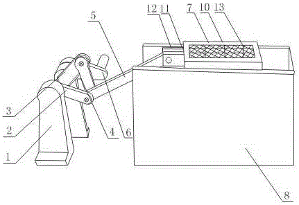
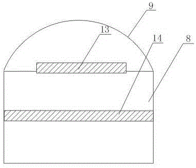
[0020] Such as figure 1 , figure 2 As shown, a separation device for purifying oil drilling fluid includes two parallel pillars 1, connecting rod A2, connecting rod B3, and connecting rod C4 in a triangular structure formed by sequentially hinged head to tail, and also includes connecting rods B3, The pull rod 5 between the connecting rods C4 and one end of which is hinged with the connecting rod B3 and the connecting rod C4 respectively, also includes a rotating disk 6 fixed on the side of the pillar 1; the rotating disk 6, the pillar 1, the connecting rod A2, and the connecting rod B3 are connected through a rotating shaft; It also includes a sieve tray 7 hinged to the other end of the pull rod 5, and a sieve box 8 arranged below the sieve tray 7. The sieve box 8 is a cavity structure with an upper surface and a side opening. Both sides of the upper surface; also includes a protective cover 9 arranged on the upper end of the screen box 8, and the opening of the lower end o...

Embodiment 2

[0023] In this embodiment, on the basis of Embodiment 1, an observation port is opened on the protective cover 9 .

[0024] The observation port arranged on the protective cover 9 is convenient for the staff to observe the working dynamics of the sieve tray 7, and repair it in time when the sieve tray 7 breaks down.

Embodiment 3

[0026] In this embodiment, on the basis of Embodiment 1 or Embodiment 2, the sieve tray 7 includes a sieve body 10, a connecting section 11 fixed at one end of the sieve body 10, and the connecting section 11 is composed of two connecting rods 12 arranged parallel to each other. , one end of the connecting rod 12 is fixed on the screen body 10; the tie rod 5 is hinged in two connecting rods 12 arranged parallel to each other; the screen body 10 is a cuboid cavity structure with upper and lower openings, and also includes a The first screen 13 in the cavity.

[0027] The pull rod 5 in this embodiment is hinged in two connecting rods 11 arranged parallel to each other, so that the movement of the pull rod 5 can drive the screen tray 7 to move left and right along the upper surface of the screen box 8 . The first screen 13 arranged in the screen body 10 plays a role of preliminary filtering of petroleum mud.


PUM


Abstract

The invention provides a separation device for purifying petroleum drilling fluid. The separation device comprises two struts, a connecting rod A, a connecting rod B, a connecting rod C, a pull rod, a turntable, a sieve disc, a sieve box and a protection cover, wherein the two struts are in parallel arrangement; the connecting rod A, the connecting rod B and the connecting rod C are in sequential end-to-end hinging connection and form a triangular structure; the pull rod is arranged between the connecting rod B and the connecting rod C; one end of the pull rod is hinged to the connecting rod B and the connecting rod C; the turntable is fixed on the side surfaces of the struts; the turntable, the struts, the connecting rod A and the connecting rod B are connected through a rotating shaft; the sieve disc is hinged to the other end of the pull rod; the sieve box is arranged under the sieve disc; the sieve box is of a cavity structure provided with openings at the upper surface and one side surface; the sieve disc is glidingly arranged at the two sides of the upper surface of the sieve box; the protection cover is arranged at the upper end of the sieve box; and an opening formed in the lower end of the protection cover is matched with the opening formed in the upper surface of the sieve box. The petroleum drilling fluid can be uniformly filtered through the leftward and rightward movement of the sieve box, and larger solid-phase particles can be effectively blocked outside the sieve box.

Description

technical field [0001] The invention relates to a separation device, in particular to a separation device for purifying oil drilling fluid. Background technique [0002] The shale shaker for oil drilling is an essential equipment in drilling. The drilling fluid circulated from the downhole to the surface must first pass through the shale shaker to remove solid particles with larger diameters before entering the desander or desilter. , to further reduce the solid phase content in the mud and play a role in mud purification. However, the traditional vibrating screen has a large screen body and poor screening efficiency, which has an adverse effect on the sieved particles after screening and the processing capacity of the vibrating screen. Contents of the invention [0003] In order to solve the defects of poor screening efficiency and unsatisfactory screening effect, the present invention provides a separation device for purifying petroleum drilling fluid. [0004] Technic...

Claims


Application Information

Patent Timeline
Patent Type & Authority Applications(China)
IPC IPC(8): E21B21/06
Inventor 周斌
Owner CHENGDU GAOPU PETROLEUM ENG TECH
Why Eureka
Try Eureka