
Check stop valve

A cut-off valve and check technology, applied in the direction of control valves, valve devices, functional valve types, etc., can solve the problems of high manufacturing level requirements, complex assembly process, and high cost

Inactive Publication Date: 2015-10-21
FLUOROSEAL SPECIALTY VALVES SUZHOU
View PDF5 Cites 1 Cited by
  • Summary
  • Abstract
  • Description
  • Claims
  • Application Information

AI Technical Summary

Problems solved by technology

This technical solution realizes the non-return function by installing a check valve core inside the stop valve, which requires a high level of manufacturing, and the assembly process is very complicated and the cost is relatively high

Method used


Image

  • Check stop valve
  • Check stop valve
  • Check stop valve

Examples


Embodiment Construction

[0018] The present invention will be further described below in conjunction with accompanying drawing.

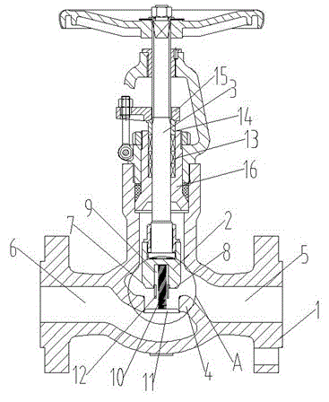
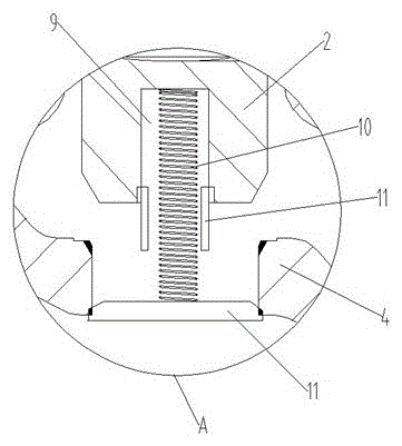
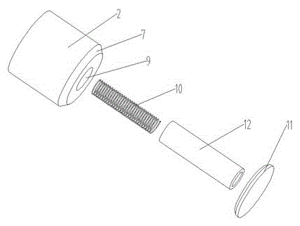
[0019] like figure 1 As described above, a check valve includes a valve body 1, a valve disc 2, and a valve stem 3 for driving the valve disc 2 to move up and down in a straight line. The valve body 1 is provided with an isolation inner wall 4 with an opening, and the isolation inner wall The two sides of 4 form the inlet cavity 5 and the outlet cavity 6 respectively, and the inlet cavity 5 and the outlet cavity 6 are connected through the opening. Fitted sealing slope 7 and bottom 8, the solution of this embodiment is to open a limit hole 9 on the bottom 8, a spring 10 is connected to the inner wall of the limit hole 9, and the other end of the spring 10 opposite to the limit hole 9 is connected to a The non-return member 11 can cover the opening of the isolation inner wall 4 . When the sealing slope 7 is located above the isolation inner wall 4 , the spring 10 is in a co...


PUM


Abstract

The invention discloses a check stop valve which is good in check effect. According to the technical scheme, the check stop valve comprises a valve body, a valve clack and a valve rod used for driving the valve clack to do the vertical linear motion, and an isolation inner wall with an opening is arranged in the valve body; an inlet cavity and an outlet cavity are formed on the two sides of the isolation inner wall respectively, and are communicated through the opening; the lower end of the valve clack is a working portion in an inverted circular truncated cone shape, and the working portion comprises a sealing inclined surface and a bottom; the sealing inclined surface can be tightly attached to the isolation inner wall, and a limiting hole is formed on the bottom; a spring is connected to the inner wall of the limiting hole, and the other end, opposite to the limiting hole, of the spring is connected with a check part capable of covering the opening of the isolation inner wall; and when the sealing inclined surface is located above the isolation inner wall, the spring is in the shrinkage state, and the check part covers the opening. The check stop valve can effectively prevent fluid from flowing back, and the manufacturing cost is low.

Description

technical field [0001] The invention relates to the technical field of valves, in particular to a stop valve with check effect. Background technique [0002] Globe valve refers to the valve in which the closing part (disc) moves along the centerline of the valve seat, and the valve disc moves linearly along the centerline of the valve seat. Since the opening or closing stroke of the valve stem of this type of valve is relatively short, and it has very reliable The cut-off function of the valve seat, and because the change of the valve seat port is proportional to the stroke of the valve disc, it is very suitable for the adjustment of the flow rate. Therefore, this type of cut-off valve is very suitable for cutting or regulating and throttling. At present, the globe valve usually includes a valve body, a valve disc, and a valve stem for driving the valve disc to move up and down in a straight line. The valve body is provided with an isolated inner wall with an opening. The t...

Claims


Application Information

Patent Timeline
Patent Type & Authority Applications(China)
IPC IPC(8): F16K15/06F16K15/18
CPCF16K15/063F16K15/18
Inventor 田洪卫
Owner FLUOROSEAL SPECIALTY VALVES SUZHOU
Learn More