
Full-operating pre-coagulating type heat-source tower device

A technology of heat source tower and full working conditions, applied in the direction of machine operation, direct contact heat exchangers, heating methods, etc., can solve problems such as large energy consumption, frosting in heating, and increased solution regeneration load. Achieve the effects of improving overall performance, reducing consumption, and reducing the load of solution regeneration

Active Publication Date: 2015-10-21
SOUTHEAST UNIV
View PDF5 Cites 5 Cited by
  • Summary
  • Abstract
  • Description
  • Claims
  • Application Information

AI Technical Summary

Benefits of technology

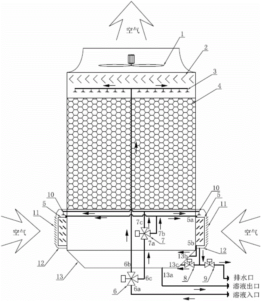
The present invention is a heat source tower device that operates efficiently in both summer and winter conditions. In the summer, it reduces the amount of cooling water needed for the unit by using a finned tube heat exchanger. In the winter, it reduces the moisture in the air entering the heat source tower, which decreases the load on the heat pump unit and improves its overall performance. This leads to energy savings and water conservation.

Problems solved by technology

This patented describes two types of solutions used in buildings' air conditioner (Air Condition) systems - one refrigerant cycle plus another liquid phase change loop circulator system called Heat Panel System(HPS). These options aim to achieve higher efficacy at warming compared to traditional methods like Air Source Chilling Compound (ACC), while also reducing costs associated with maintenance work over time due to frequent replacements of equipment. Additionally, these alternatives require less expensive materials and involve complex processes involving multiple steps.

Method used


Image

  • Full-operating pre-coagulating type heat-source tower device

Examples


Embodiment Construction

[0019] The technical solution of the present invention will be further described below in conjunction with the embodiments and the accompanying drawings.

[0020] The present invention provides a pre-condensation type heat source tower device operating under all working conditions, the principle diagram of which is as follows figure 1 As shown, the heat source tower includes a heat source tower body and a main solution circuit, a precondensation and spray frost suppression circuit and an air circuit arranged in the tower body.

[0021] The main solution circuit includes the liquid distributor 3, the filler 4, the liquid collection tank 13, the first electric three-way valve 6 and its connecting pipes arranged sequentially from top to bottom; in the main solution circuit, the solution inlet port of the heat source tower is connected to the first The inlet 6a of the electric three-way valve, the first outlet 6b of the first electric three-way valve are connected to the inlet of ...


PUM


Abstract

The invention discloses a full-operating pre-coagulating type heat-source tower device. The full-operating pre-coagulating type heat-source tower device comprises a main solution loop, a pre-coagulating and spraying frost restrain loop and an air loop, wherein the main solution loop and the pre-coagulating and spraying frost restrain loop are connected in parallel; solutions or cooling water enters from the solution inlet end of a heat-source tower, and is divided into two parts in a parallel-connection mode after passing through a first electric driving three-way valve, and then the two parts enter the main solution loop and the pre-coagulating and spraying frost restrain loop respectively, and are gathered in a liquid collecting reservoir. The solution regeneration load of a heat-source tower heat pump unit under various winter heating operating conditions can be reduced; the solution renewable energy consumption is reduced; meanwhile, cooling water consumption in the summer refrigerating operation is reduced; the winter and summer comprehensive performance of a heat-source tower heat pump system is improved.

Description


Claims


Application Information

Patent Timeline
Owner SOUTHEAST UNIV
Learn More