Optical device frequency response measurement apparatus and method

A frequency response and measurement device technology, applied in the field of optical measurement, can solve the problem of high cost and achieve the effect of low requirements and low cost

Active Publication Date: 2015-10-21
NANJING UNIV OF AERONAUTICS & ASTRONAUTICS
View PDF7 Cites 31 Cited by
  • Summary
  • Abstract
  • Description
  • Claims
  • Application Information

AI Technical Summary

Problems solved by technology

[0004] Purpose of the invention: In order to overcome the deficiencies in the prior art, the present invention provides a device and method for measuring the frequency resp

Method used


Image

  • Optical device frequency response measurement apparatus and method
  • Optical device frequency response measurement apparatus and method
  • Optical device frequency response measurement apparatus and method

Examples


Embodiment Construction

[0029] The present invention will be further described below in conjunction with the accompanying drawings.
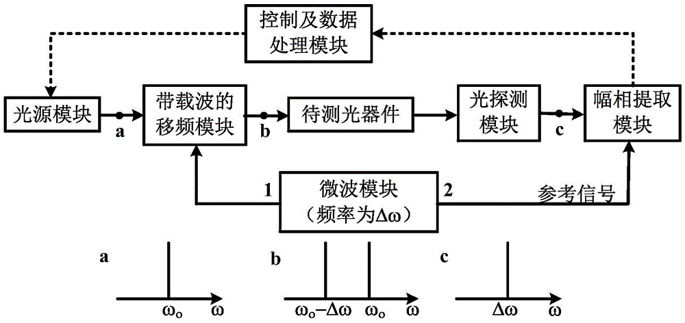
[0030] The idea of ​​the present invention is: combine the photon frequency shifting technology and the RF signal amplitude and phase extraction technology to realize the improvement of measurement accuracy; use the frequency shifting module with carrier and the optical detection module to realize the down-conversion function of fixed frequency, and convert the frequency-sweeping optical signal Converted to a fixed frequency radio frequency signal.

[0031] figure 1 It shows a structure of the optical device frequency response measurement system of the present invention. As shown in the figure, the measurement system includes a light source module, a frequency shift module with a carrier, an optical device to be tested, a light detection module, an amplitude and phase extraction module, and a control and The data processing module; the light source module outputs a sing...


PUM


Abstract

The invention discloses an optical device frequency response measurement method and a system. The method is characterized in that an optical carrier wave signal of a single wavelength is input into a frequency shift module with a carrier wave so that an optical detection signal with a carrier wave component and a frequency shift component is acquired; after the signal passes through a device to be detected, a radio frequency signal is acquired through a beat frequency of an optical detection module; a radio frequency amplitude phase extraction module whose working frequency is the same with a frequency shift amount is used to extract an amplitude and a phase information of the radio frequency signal so that combination amplitude frequency response and phase frequency response of an optical device to be detected at two frequency component positions of the optical detection signal are obtained; through calculation, the amplitude frequency response and the phase frequency response at the two frequency component positions are acquired respectively; a wavelength of the optical carrier wave signal is changed and the above processes are repeated so that frequency response of the optical device to be detected is acquired. The invention also discloses an optical device frequency response measurement system. Compared to the prior art, by using the method and the system, the amplitude phase extraction module is only requested to measure a fixed single frequency point so that cost is greatly reduced and simultaneously a bandpass device can be measured.

Description

technical field [0001] The invention relates to the technical field of optical measurement, in particular to a measuring device and method for the frequency response of an optical device. Background technique [0002] In recent years, with the rapid development of laser technology, photonic systems have been widely used. During the development, production, testing and application of high-precision optical devices, high-precision optical device frequency response testing technology is essential. However, the existing optical device frequency response testing technology is difficult to perform multi-dimensional and high-precision characterization of high-precision optical devices (such as high-Q microresonators such as microrings and microspheres). At present, LUNA Company of the United States is the only company that produces commercial optical vector analyzers. Its OVA5000 test instrument can measure the multidimensional frequency response of optical devices (such as amplitu...

Claims


Application Information

Patent Timeline
IPC IPC(8): G01M11/02
Inventor 卿婷潘时龙薛敏张蒙
Owner NANJING UNIV OF AERONAUTICS & ASTRONAUTICS
Why Eureka
Try Eureka