Cable on-line detector

A detector and cable technology, applied in the field of cable online detectors, can solve the problems of cumbersome operating procedures, inability to perform short-circuit fault testing, and high manufacturing costs, so as to improve detection efficiency, solve online testing problems, and reduce workload.

Active Publication Date: 2015-10-21
CHINA ELECTRONICS TECH GRP NO 7 RES INST
View PDF8 Cites 7 Cited by
  • Summary
  • Abstract
  • Description
  • Claims
  • Application Information

AI Technical Summary

Problems solved by technology

[0009] In the above solution, although the multimeter can test the fault of the cable, since the two test leads of the multimeter must touch the two ends of the cable during the test, when the cable connected to the device is long or one end is not easy to disassemble or is difficult to touch, use When the multimeter tests the cable fault, the operation procedure becomes very cumbersome; while the online test method has the defects that the short circuit fault test cannot be performed and the manufacturing cost is high

Method used


Image

  • Cable on-line detector
  • Cable on-line detector
  • Cable on-line detector

Examples


Embodiment 1

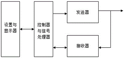
[0046] like Figure 4 As shown, the online detector includes a signal generator, a first cable access terminal A, a second cable access terminal B, an open circuit test resistor R2, a short circuit test resistor R2', a switch K, a rectifier circuit, a comparator and an indicating circuit ; wherein the output terminal of the signal generator is connected to the first cable access terminal A, the second cable access terminal B is connected to the indicator circuit through the rectifier circuit, the comparator, and the open circuit test resistor R2 and the short circuit test resistor R2' are connected through the switch K Connected to the second cable access terminal B, the signal generator, the open circuit test resistor R2, the short circuit test resistor R2' and the indicating circuit are grounded.

[0047] like Figure 5 , 6 , 7, in this embodiment, the signal generator includes 3 NAND gates D1A, D1B, D1C, resistor R1 and capacitor C1, the NAND gate D1A is connected with ...


PUM


Abstract

The invention relates to a cable on-line detector. The cable on-line detector comprises a signal generator, a first cable accessing end A, a second cable accessing end B, an open-circuit test resistor R2, a short-circuit test resistor R2', a change-over switch K, a rectifier circuit, a comparator and an indicating circuit; and an output end of the signal generator is connected with the first cable accessing end A, the second cable accessing end B is connected with the indicating circuit through the rectifier circuit and the comparator, the open-circuit test resistor R2 and the short-circuit test resistor R2' are connected with the second cable accessing end B through the change-over switch K, and the signal generator, the open-circuit test resistor R2, the short-circuit test resistor R2' and the indicating circuit are grounded. The cable on-line detector is advantageous in that 1) the workload of equipment detachment during equipment testing or maintenance is reduced, 2) cable detection efficiency is improved, and 3) manufacturing cost is reduced.

Description

technical field [0001] The invention relates to the field of cable maintenance, and more specifically, to a cable online detector. Background technique [0002] In an electronic system with dense equipment, whether the cable connection between equipment is normal or not directly affects the working performance of the system. Therefore, in the testing and maintenance of electronic systems, how to use a simple method to quickly judge the fault of the cable is of great significance. In the prior art, commonly used methods for judging cable faults include a multimeter method and an online test method. [0003] like figure 1 As shown, the multimeter is composed of a power supply battery (BATTERY), an indicator light (LED), and a buzzer. Two tested cables A1B1 and A2B2 such as figure 2 As shown, where C1 is an arbitrary point in the middle of cable A1B1, and C2 is an arbitrary point in the middle of cable A2B2. [0004] When using a multimeter for an open circuit fault test,...

Claims


Application Information

Patent Timeline
Patent Type & Authority Applications(China)
IPC IPC(8): G01R31/08
Inventor 符建名
Owner CHINA ELECTRONICS TECH GRP NO 7 RES INST
Why Eureka
Try Eureka