
A Servo Pressure Control System

A servo pressure and control system technology, applied in the field of control, can solve problems such as poor real-time performance and complicated programming, and achieve the effect of low cost, simple control method, and good real-time continuity

Active Publication Date: 2018-02-16
BOZHON PRECISION IND TECH CO LTD
View PDF7 Cites 0 Cited by
  • Summary
  • Abstract
  • Description
  • Claims
  • Application Information

AI Technical Summary

Problems solved by technology

But the disadvantages of this control method are: it takes up a lot of precious time of the CPU, and complex software codes need to be written, and the real-time performance is poor, so it should be limited to a very low speed in actual use.

Method used


Image

  • A Servo Pressure Control System
  • A Servo Pressure Control System

Examples


Embodiment Construction

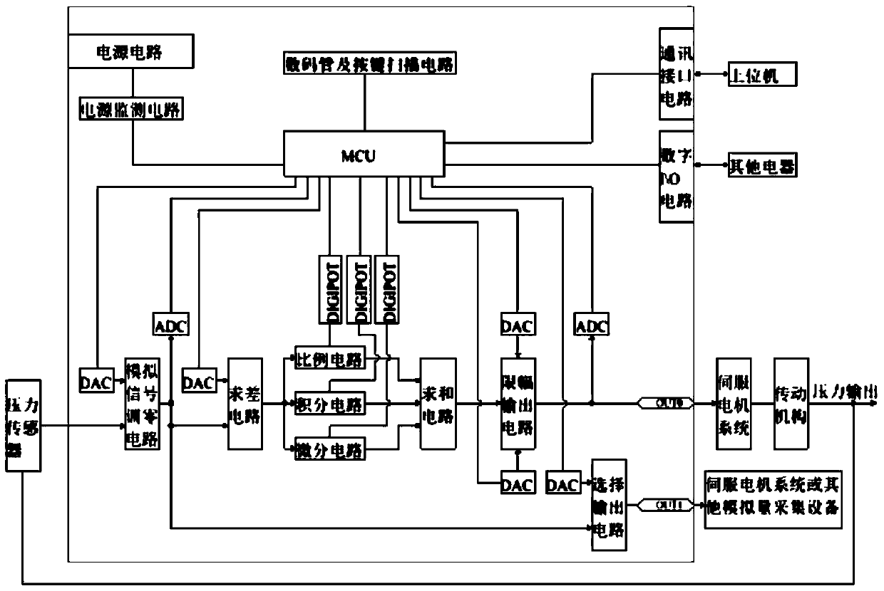
[0033] Such as figure 1 , a servo pressure control system, including a servo pressure controller, a pressure sensor, and a servo motor.

[0034] Such as figure 1 , the servo pressure controller includes MCU and single chip microcomputer minimum system circuit, digital tube and button scanning circuit, communication interface circuit, analog signal zero adjustment circuit, ADC circuit, DAC circuit, analog signal PID adjustment circuit, digital potentiometer circuit, analog Signal limiting output circuit, signal selection output circuit, digital I / O circuit.

[0035] Such as figure 1 , in the above servo pressure controller, the servo pressure controller is connected to the upper computer through a communication interface circuit.

[0036] Such as figure 1 , in the above servo pressure controller, the servo pressure controller is connected to the control panel through a digital tube and a button scanning circuit.

[0037] Such as figure 1 , in the above servo pressure cont...


PUM


Abstract

A servo pressure control system, including a servo pressure controller, a pressure sensor, and a servo motor; the servo pressure controller includes an MCU, an ADC circuit, a DAC circuit, an analog input signal zeroing circuit, and an analog signal PID adjustment circuit; the pressure sensor will reflect The voltage signal of the pressure value is sent to the servo pressure controller, the voltage signal reflecting the user command is sent to the servo pressure controller, the voltage signal reflecting the pressure value is sent to the ADC circuit after the analog signal zeroing circuit, and the analog signal PID adjustment circuit is used to reflect the pressure and The deviation of the two voltage signals of the target pressure is processed by proportionality, integration and differentiation, and the obtained voltage signal is sent to the ADC circuit and the servo motor system. The servo pressure controller also includes an analog signal limiting output circuit that limits the delivered voltage signal within a certain range. The invention solves the difficulty of pressure control in the automation industry, and greatly improves the real-time response and control precision.

Description

Technical field: [0001] The invention relates to the technical field of control, in particular to a servo pressure control system. Background technique: [0002] In automatic equipment, it is often necessary to clamp or press products with a constant force. In the existing engineering application, the servo motor is used to control the constant force output of the motion mechanism, and the torque control mode of the servo motor can be used, and a pressure sensor is added at the output end to monitor the output force. But this is an open-loop system. Due to the error introduced by the transmission mechanism and the amplification of the motor torque error, there is a certain difference between the force output at the output end and the given amount, and the sensitivity of the adjustment is very poor. The pressure sensor only monitors the output. The size of the force cannot play a feedback role. [0003] Due to the obvious shortcomings of the above control modes, in practica...

Claims


Application Information

Patent Timeline
Patent Type & Authority Patents(China)
IPC IPC(8): G05D16/20
Inventor 吕绍林马金勇孙卫东赵永存戴庆波
Owner BOZHON PRECISION IND TECH CO LTD
Learn More