Deep spray coating rotary cup

A multi-layer, internal and external rotation technology, applied in the direction of coating, spraying device, device for coating liquid on the surface, etc., can solve the problems of unbalanced outward force, uneven surface thickness, waste of raw materials, etc., and achieve the balance of outward force , uniform coating and easy assembly

Inactive Publication Date: 2008-04-09
TIANJIN YANGQI ELECTROMECHANICAL TECH DEV
View PDF0 Cites 5 Cited by
  • Summary
  • Abstract
  • Description
  • Claims
  • Application Information

AI Technical Summary

Problems solved by technology

[0002] At present, it is used for various pipes, and the inner paint spraying of different pipe diameters has always been a single-layer spraying cup. There are several micropores on the surface of the rotary cup, and the paint is injected into the rotary cup through the feeding pipe. Under the high-speed rotation of the motor shaft, the paint is distributed in the rotary cup and then sprayed out through the micropores. Uniformity and unbalanced external force will affect the service life of high-speed motors, fail to meet the technical requirements of coating design, and cause a lot of waste of raw materials

Method used


Image

  • Deep spray coating rotary cup
  • Deep spray coating rotary cup

Examples


Embodiment 1

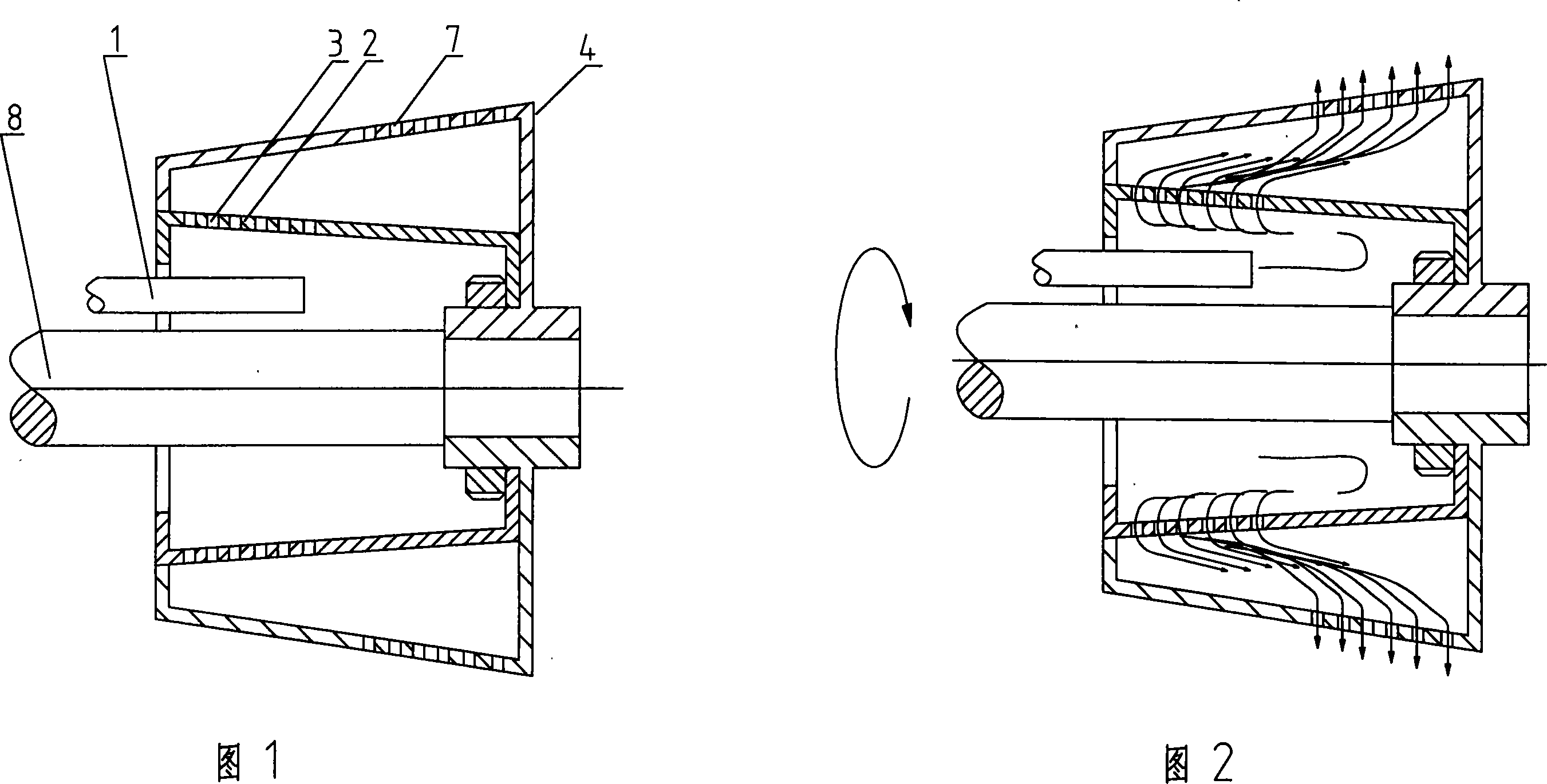
[0016] Example 1, as shown in Figure 1-2, the paint is injected into the inner rotating cup 2 through the feeding pipe 1, and the paint is evenly distributed in the inner rotating cup under the high-speed rotation of the motor shaft 8, and then sprayed out through the discharge micropores 3 on its surface , the paint enters the outer rotating cup 4, and the paint is evenly distributed in the outer rotating cup under the high-speed rotation of the motor shaft, and then sprayed out again through the discharge micropores 7 on the surface, so that the paint is sprayed on the inner wall of the steel pipe in a mist form, forming Uniform coating.

Embodiment 2

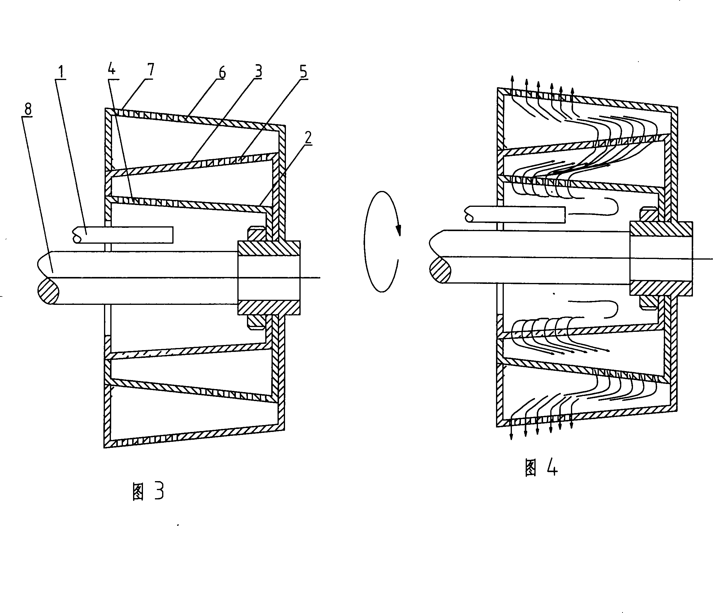
[0017] Example 2, as shown in Figure 3-4, is the working principle of the three-layer rotary cup: the paint is injected into the inner rotary cup 2 from the delivery pipe 1, and the paint passes through the surface of the inner rotary cup after the motor shaft 8 rotates at a high speed The discharge microholes 4 are sprayed into the middle rotary cup 3, and the paint is evenly distributed in the middle rotary cup 3 under the high-speed rotation of the motor shaft, and then sprayed out again into the outer rotary cup 6 through the discharge microholes 5 on its surface Under the high-speed rotation of the motor shaft, the paint is evenly distributed in the outer rotary cup 6 and then sprayed out again through the discharge micropores 7 on its surface, so that the paint is sprayed on the inner wall of the steel pipe in a mist form to form a uniform coating. When spraying, the paint is uniformly mixed and dispersed through the inner rotary cup cavity and then sprayed into the outer...


PUM


Abstract

The invention relates to a multi-layer type spraying spinning cup, which comprises the spinning cup arranged on an electric or pneumatic motor axle. The invention is characterized in that the spinning cup on the motor axle has at least two layers, material outlet flow channels are evenly distributed on the surface of the spinning cup, the spinning cup is divided into an inner spinning cup and an outer spinning cup, and the inner spinning cup and the outer spinning cup are fixed and connected into a whole through a thread after being suited. The invention has the advantages that after being uniformly mixed and dispersed through an inner layer of spinning cup cavity body when being sprayed coating materials are sprayed to the inside of the outer spinning cup through micro pores, after being further uniformly mixed through the inner spinning cup cavity body, the coating materials are sprayed to the inside of a steel pipe through the micro pores, and the coating materials are uniformly sprayed to the inside of a pipe into a fog shape, to form a uniform coating layer. The device solves the deficiency of a single-layer cup, and the invention provides a spraying device with reasonable structure, convenient assembly, balanced outward force, energy conservation, and uniform coating layer for the spray coating of the pipe inside.

Description

technical field [0001] The invention belongs to pipe inner wall spraying equipment, in particular to a multi-layer spraying rotary cup. Background technique [0002] At present, it is used for various pipes, and the inner paint spraying of different pipe diameters has always been a single-layer spraying cup. There are several micropores on the surface of the rotary cup, and the paint is injected into the rotary cup through the feeding pipe. Under the high-speed rotation of the motor shaft, the paint is distributed in the rotary cup and then sprayed out through the micropores. Uniformity and unbalanced outward force will affect the service life of high-speed motors, fail to meet the technical requirements of coating design, and cause a lot of waste of raw materials. Contents of the invention [0003] The object of the present invention is to overcome the shortcomings of the above-mentioned technologies, and provide a multi-layer spraying rotary cup with reasonable structur...

Claims


Application Information

Patent Timeline
Patent Type & Authority Applications(China)
IPC IPC(8): B05B13/06B05B3/12B05C7/02
Inventor 宋扬
Owner TIANJIN YANGQI ELECTROMECHANICAL TECH DEV
Why Eureka
Try Eureka