Invisible laser system and optical path visualization method thereof

A laser and visible light technology, applied in the laser field, can solve problems such as time-consuming debugging process, inability to see and debug optical path, high radiation risk, etc., to achieve the effect of eliminating radiation risk, avoiding blindness, and improving efficiency

Active Publication Date: 2015-10-21
BOE TECH GRP CO LTD +1
View PDF6 Cites 6 Cited by
  • Summary
  • Abstract
  • Description
  • Claims
  • Application Information

AI Technical Summary

Problems solved by technology

However, this infrared observer can only observe a certain point of the optical path and cannot see and debug the

Method used


Image

  • Invisible laser system and optical path visualization method thereof
  • Invisible laser system and optical path visualization method thereof
  • Invisible laser system and optical path visualization method thereof

Examples


Embodiment Construction

[0064] The specific implementation of the invisible laser system and its optical path visualization method of the present disclosure will be described in detail below in conjunction with the accompanying drawings. The drawings in the present disclosure schematically illustrate the structure, part and / or step related to the invention point, but not or only partially illustrate the structure, part and / or step irrelevant to the invention point.

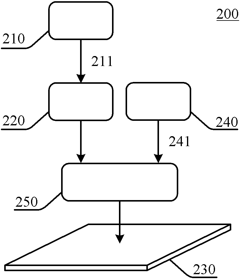
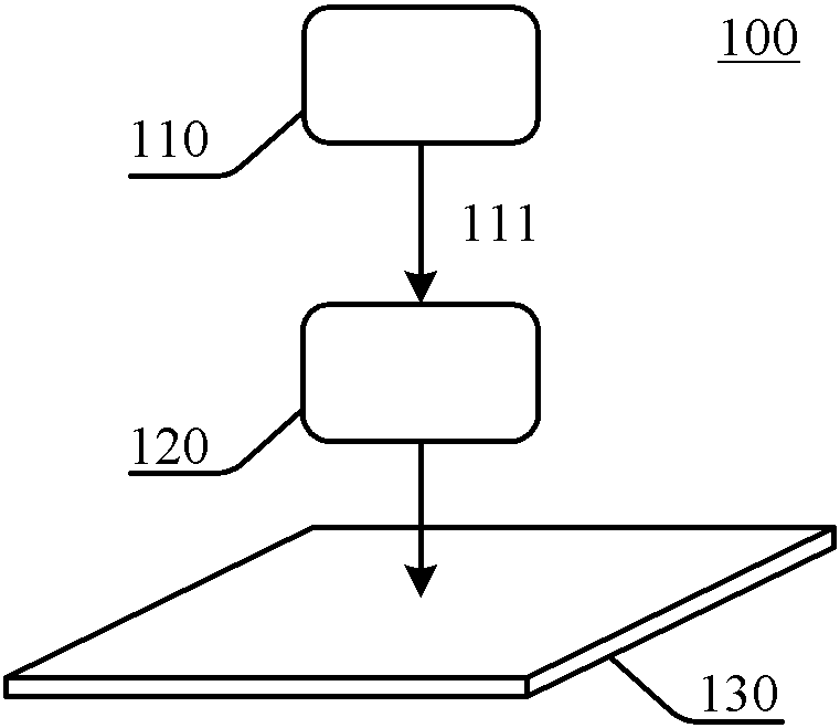
[0065] figure 2 A schematic diagram of an invisible laser system 200 according to an embodiment of the present disclosure is shown. The invisible laser light 211 emitted by the invisible laser generator 210 passes through the laser adjusting component 220 and then reaches the surface of the object 230 to be processed.

[0066] The invisible laser system 200 also includes a generator 240 that generates visible light. The visible light generator 240 generates visible light 241. The visible light 241 may be visible laser light or visible natu...


PUM


Abstract

The invention discloses an invisible laser system and an optical path visualization method thereof and belongs to the technical field of laser. The invisible laser system comprises an invisible laser generator for generating invisible laser; a visible light generator for generating visible light; and an optical path visualization component which is arranged in light paths of the invisible laser and the visible light, and at least comprises a first incoming end, a second incoming end and a first outgoing end, wherein the invisible laser is incident at the first incoming end; the visible light is incident at the second incoming end; and all invisible laser and at least a part of visible light are output in parallel at the first outgoing end. According to the invisible laser system and the optical path visualization method thereof, all invisible laser only exists in the direction parallel to the light path of the visible light, and the invisible laser does not exist in other directions, thereby eliminating radiation risk.

Description

Technical field [0001] The present disclosure relates to the field of laser technology, and in particular to an invisible laser system and a method for visualizing its optical path. Background technique [0002] Invisible lasers are widely used in device processing and other fields. For example, in the liquid crystal display (LCD) manufacturing process, such as Nd: YAG laser (wavelength 1.064μm), CO 2 Laser (wavelength 10.6μm) invisible lasers are often used to cut glass substrates, repair display panels, cut lines, and make polysilicon active layers. When the laser is installed and poor processing occurs, engineers are required to debug the laser. However, since the laser light emitted by this laser is invisible, this brings inconvenience and radiation risk to engineers when debugging the laser. [0003] figure 1 A schematic diagram of an invisible laser system 100 is shown. The invisible laser 111 emitted by the invisible laser generator 110 passes through the laser adjusting ...

Claims


Application Information

Patent Timeline
IPC IPC(8): H01S1/00
CPCB23K26/02B23K26/042B23K26/0608B23K26/0613B23K26/0652B23K26/38B23K26/402B23K2103/54C03B33/0222C03B33/091G02B27/1006G02B27/126G02B26/0816G02B27/283G02F1/1303
Inventor 王海平郭栋钱红闫旭
Owner BOE TECH GRP CO LTD
Why Eureka
Try Eureka