Dust collection device for vacuum cleaners

A dust collection device and vacuum cleaner technology, which is applied in the direction of suction filters, etc., can solve the problems of affecting the dust collection efficiency of the vacuum cleaner, reducing the suction force of the vacuum cleaner, and high component manufacturing costs, achieving fast and thorough separation of dust and gas, increased dust collection capacity, and space saving Effect

Active Publication Date: 2017-12-01
JIANGSU MIDEA CLEANING APPLIANCES
View PDF7 Cites 0 Cited by
  • Summary
  • Abstract
  • Description
  • Claims
  • Application Information

AI Technical Summary

Problems solved by technology

[0003] Because there is a corner at the connection between the air guide pipe and the dust cup, the sealing between the cyclone separator and the dust cup is poor, and the air guide pipe is relatively long, all of which lead to a decrease in the suction force of the vacuum cleaner when it is working, thus affecting the dust collection of the vacuum cleaner Efficiency, and component manufacturing costs are also high

Method used


Image

  • Dust collection device for vacuum cleaners
  • Dust collection device for vacuum cleaners
  • Dust collection device for vacuum cleaners

Examples


Embodiment Construction

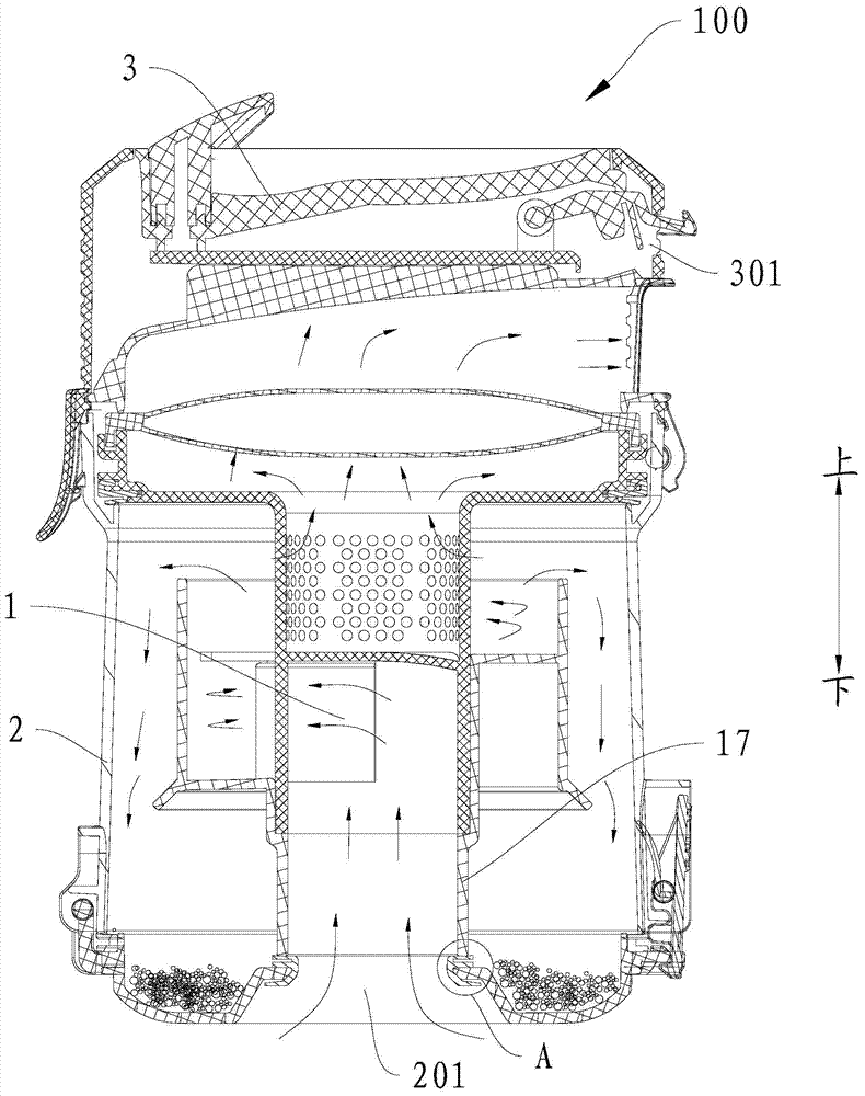
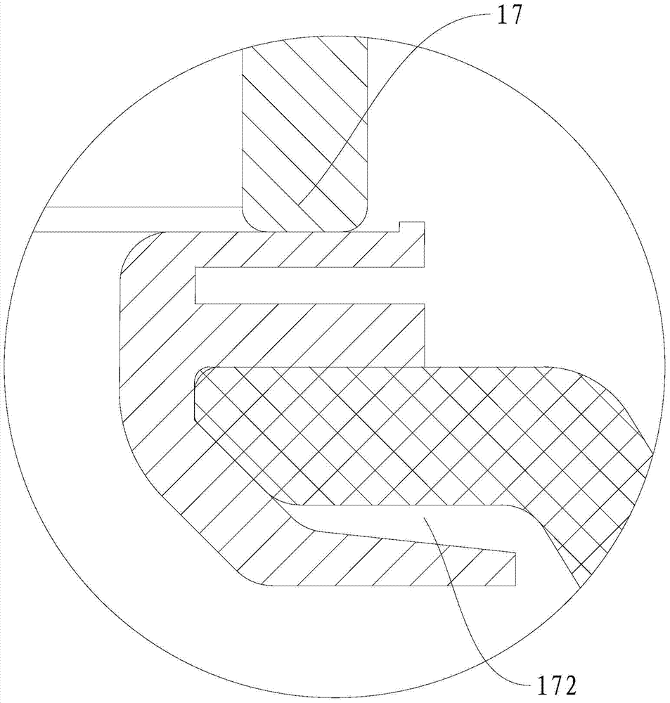
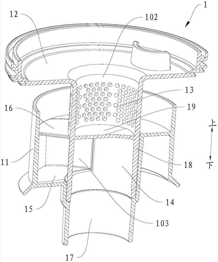
[0028] Embodiments of the present invention are described in detail below, examples of which are shown in the drawings, wherein the same or similar reference numerals designate the same or similar elements or elements having the same or similar functions throughout. The embodiments described below by referring to the figures are exemplary and are intended to explain the present invention and should not be construed as limiting the present invention.

[0029] In describing the present invention, it should be understood that the terms "center", "longitudinal", "transverse", "length", "width", "thickness", "upper", "lower", "front", " Orientation or position indicated by "back", "left", "right", "vertical", "horizontal", "top", "bottom", "inner", "outer", "clockwise", "counterclockwise", etc. The relationship is based on the orientation or positional relationship shown in the drawings, and is only for the convenience of describing the present invention and simplifying the descrip...


PUM


Abstract

The invention discloses a dust collecting device of a vacuum cleaner, which comprises: a dust cup, a cyclone separator and an upper cover of the dust cup. The bottom wall of the dust cup is provided with an air inlet; the cyclone separator is arranged in the dust cup, and the cyclone separator has a cyclone separator inlet and a cyclone separator outlet, and the cyclone separator inlet is connected with the air inlet; the dust cup upper cover is set on On the dust cup, the upper cover of the dust cup is provided with an air outlet communicating with the outlet of the cyclone separator. According to the dust collecting device of the vacuum cleaner in the embodiment of the present invention, the bottom air intake is adopted, which greatly shortens the distance from the cyclone separator inlet to the air inlet, and shortens the length of the air guide pipe in the vacuum cleaner communicating with the air inlet, reducing power loss , save enough space for the whole vacuum cleaner and save manufacturing cost. In addition, the suction of the whole vacuum cleaner with the dust collecting device will no longer drop quickly due to the clogging of filter cotton, which will greatly improve the separation efficiency and prolong the life of the filter cotton. cleaning cycle.

Description

technical field [0001] The invention relates to the field of household appliances, in particular to a dust collecting device of a vacuum cleaner. Background technique [0002] The dust collection device in the related art generally includes a cyclone, a central filter placed in the cyclone for filtering dust and other dirt, and an air guide pipe tangentially connected to the outer wall of the cyclone, and the air guide pipe is connected to the side of the dust cup. The wall air inlet and the side wall of the cyclone. The side wall air intake requires a long air duct to connect the outside world and the air inlet of the integrated device, and the dust-laden air enters the dust collection cup tangentially for dust and gas separation. [0003] Because there is a corner at the connection between the air guide pipe and the dust cup, the sealing between the cyclone separator and the dust cup is poor, and the air guide pipe is relatively long, all of which lead to a decrease in th...

Claims


Application Information

Patent Timeline
Patent Type & Authority Patents(China)
IPC IPC(8): A47L9/16
Inventor 刘胜辉徐权
Owner JIANGSU MIDEA CLEANING APPLIANCES
Why Eureka
Try Eureka