A slurry tank agitator

A technology of agitator and pulp, which is applied in the direction of agitator accessories, chemical instruments and methods, dissolution, etc., can solve the problems of shortened service life of agitator drive internal bearings, increased maintenance costs, sloshing of agitator shafts, etc., to achieve stable agitation operation and overall Strong stability and the effect of increasing the stirring load

Active Publication Date: 2017-03-15
江苏胜开尔工业技术有限公司
View PDF3 Cites 0 Cited by
  • Summary
  • Abstract
  • Description
  • Claims
  • Application Information

AI Technical Summary

Problems solved by technology

[0002] With the continuous development of industry, it is required to increase the size and high solid content of the pulp mixing tank to improve production efficiency. However, the existing flat paddle stirring, narrow paddle stirring, and simple folding paddle stirring have small displacement, high power consumption, and poor stability. , Stirring reaction is not uniform, easy to sink to the bottom, bringing immeasurable losses to users such as parking and production stoppage
[0003] The non-efficient design of the agitator blades increases the power of the user's motor and increases the operating cost; the unstable design of the agitator blades causes the agitator shaft to shake, shortens the service life of the inner bearing of the agitator drive, and increases the maintenance cost of the user
Generally, a set of agitators is only for one process, and the versatility is not strong. Some users need to purchase a new set of agitators due to production needs to adjust the process and change the types of products produced, resulting in low equipment utilization.
And the agitator blades are generally welded with the agitator shaft. As the service life increases, the agitator blades are corroded and eroded, and the user needs to replace spare parts. Often because the agitator blades are welded to the agitator shaft, the user is often forced to replace the agitator shaft. Let users spend money and effort

Method used


Image

  • A slurry tank agitator
  • A slurry tank agitator
  • A slurry tank agitator

Examples


Embodiment Construction

[0024] The present invention will be further described below in conjunction with the accompanying drawings and embodiments.

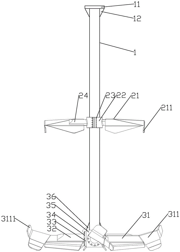
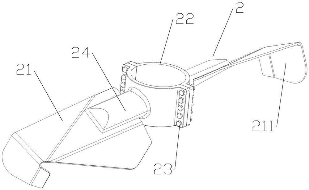
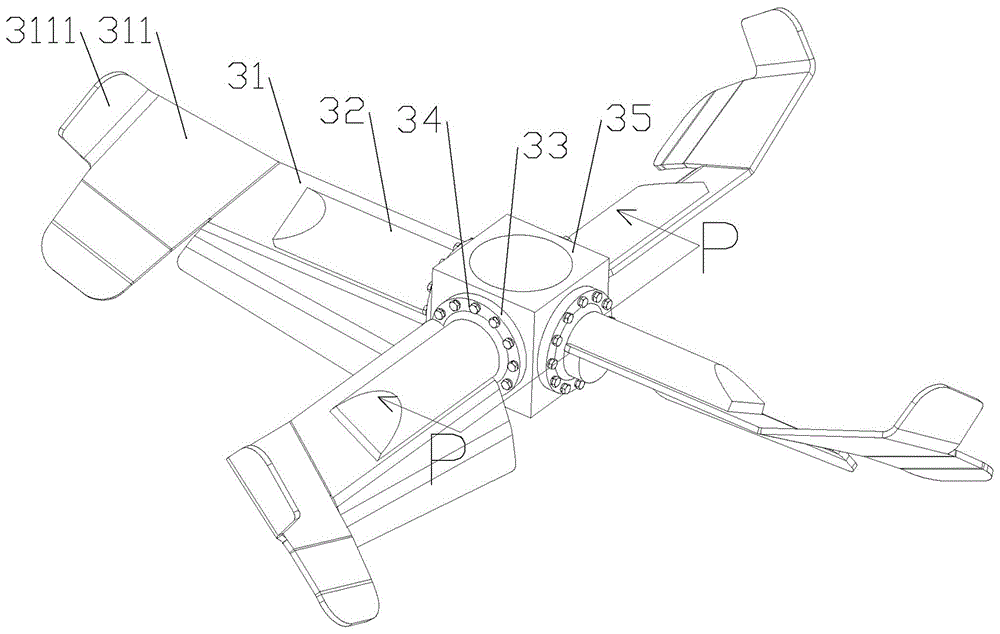
[0025] Such as Figure 1-4 Shown: a slurry tank agitator, comprising a stirring shaft 1, the top of the stirring shaft 1 is provided with a stirring shaft flange 11 and the stirring shaft flange 11 strengthens the stability of the connection with the stirring shaft 1 through the stirring shaft rib 12; The bottom end of the shaft 1 is fixed with an impeller B3, and above the impeller B3 is an impeller A2 fixed on the stirring shaft 1. The impeller A2 includes a blade A21 and a hoop-type hub 22, and two left and right halves are symmetrically distributed. Type hub 22 is tightened and fastened on the stirring shaft 1 by bolt A23, blade A21 is welded on reinforcement rib A24 and reinforcement rib A24 is welded and connected with hoop type hub 22, so that two groups of blades A21, reinforcement rib A24 and hoop type hub 22 and the corresponding bolts A23 fo...


PUM


Abstract

The invention discloses a pulp tank agitator. The pulp tank agitator comprises an agitating shaft (1), a second vane wheel (3) is fixedly arranged at the bottom end of the agitating shaft (1), and a first vane wheel (2) fixed on the agitating shaft (1) is arranged over the second vane wheel (3); the water attaining surfaces of the propeller surfaces of first vanes (21) adopted by the first vane wheel (2) bend downwards, and the tails of the first vanes (21) are provided with first flow stabilizing rings(211) which bend downwards; the water attaining surfaces of the propeller surfaces of second vanes (31) adopted by the second vane wheel (3) bend downwards, the tails of the second vanes (31) are provided with upward-bending sections (311) to push materials to move downwards in the axial direction of the agitating shaft (1) and move downwards and outwards in the radial direction of the agitating shaft (1), and meanwhile the outermost ends of the upward-bending sections (311) are provided with upward-bending second flow stabilizing rings (3111). According to the pulp tank agitator, agitating is stable and efficient, part replacing is convenient, the angle of the vanes can be regulated, and therefore the pulp tank agitator is suitable for use and popularization.

Description

technical field [0001] The invention relates to the technical field of agitation, in particular to a slurry tank agitator with stable and efficient agitation, convenient replacement of parts and the ability to adjust the blade angle. Background technique [0002] With the continuous development of industry, it is required to increase the size and high solid content of the pulp mixing tank to improve production efficiency. However, the existing flat paddle stirring, narrow paddle stirring, and simple folding paddle stirring have small displacement, high power consumption, and poor stability. , The stirring reaction is not uniform, and it is easy to sink to the bottom, which brings immeasurable losses such as parking and production stoppage to users. [0003] The non-efficient design of the agitator blades increases the power of the user's motor and increases the operating cost; the unstable design of the agitator blades causes the agitator shaft to shake, shortens the service...

Claims


Application Information

Patent Timeline
Patent Type & Authority Patents(China)
IPC IPC(8): B01F15/00
Inventor 杨胜华杨家林
Owner 江苏胜开尔工业技术有限公司
Why Eureka
Try Eureka