Perforating machine for automatically controlling perforating depth
A punching machine, deep technology, applied in the field of punching machine, can solve the problem of poor punching effect, complex structure of punching device, etc., and achieve the effect of simple structure and easy operation
- Summary
- Abstract
- Description
- Claims
- Application Information
AI Technical Summary
Problems solved by technology
Method used
Image
Examples
Embodiment 1
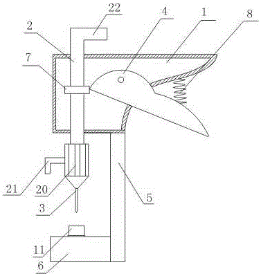
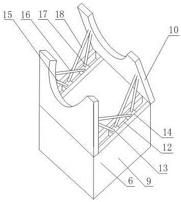
[0021] Such as figure 1 , figure 2 As shown, the punching machine for automatically controlling the drilling depth includes a fixed handle 1 with a cavity structure, a sliding rod 2 that is slidably arranged in the fixed handle 1 through the upper and lower end surface openings of the fixed handle 1, and a sliding rod 2 that is arranged at the bottom of the sliding rod 2. Drill needle 3, movable handle 4 hinged on the fixed handle 1, support rod 5 fixed on the lower end of fixed handle 1 and adjustment seat 6 connected with support rod 5; one side of fixed handle 1 is fully open, and also includes a The chuck 7 on the slide bar 2, one end of the movable handle 4 is connected with the chuck 7, and the other end runs through the side opening of the fixed handle 1 and is located outside the fixed handle 1; it also includes one end connected with the fixed handle 1 and the other end connected with the movable handle 4 The limit spring 8; the adjustment seat 6 includes a base 9, ...
Embodiment 2
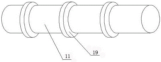
[0024] This embodiment is on the basis of embodiment 1, as image 3 As shown, retaining rings 19 are evenly distributed on the bottom rod 11 from bottom to top along the axis direction of the bottom rod 11 , and the diameter of the retaining rings 19 is larger than that of the bottom rod 11 .
[0025] When it is necessary to adjust the distance between the material to be punched and the drill pin 3, the cover 10 hinged on both sides of the upper surface of the base 9 is opened, and the bottom rod 11 is placed in the base 9. When the bottom rod 11 reaches the During proper position, cover 10 on both sides is covered, because back-up ring 19 diameters are greater than bottom rod 11 diameters, the position of bottom rod 11 will be fixed. ,
Embodiment 3
[0027] On the basis of Embodiment 1, this embodiment also includes a taper head 20 fixed at the lower end of the slide rod 2 through screw connection, and the drill needle 3 is fixed at the bottom of the taper head 20 . It also includes a handle 21 fixed on the side surface of the cone head 20 .
[0028] When the material to be punched is thick or the strength of the hand is difficult to complete the hole, while the above operation is performed, rotate the handle 21 with the other hand, and the drill needle 3 will move up and down and act on the material to be punched again, thereby assisting Finish punching.
PUM
 Abstract
Description
Claims
Application Information
 - R&D
- Intellectual Property
- Life Sciences
- Materials
- Tech Scout
- Unparalleled Data Quality
- Higher Quality Content
- 60% Fewer Hallucinations
Browse by: Latest US Patents, China's latest patents, Technical Efficacy Thesaurus, Application Domain, Technology Topic, Popular Technical Reports.
© 2025 PatSnap. All rights reserved.Legal|Privacy policy|Modern Slavery Act Transparency Statement|Sitemap|About US| Contact US: help@patsnap.com


