Welding equipment for ring-shaped metal parts

A technology for metal parts and welding equipment, applied in the field of parts processing, can solve the problems of high labor intensity of operators and low welding efficiency, and achieve the effect of making up for defects, improving efficiency and reducing labor intensity

Inactive Publication Date: 2015-10-28
CHONGQING FENGYANG ELECTROMECHANICAL
View PDF5 Cites 4 Cited by
  • Summary
  • Abstract
  • Description
  • Claims
  • Application Information

AI Technical Summary

Problems solved by technology

In the prior art, the above-mentioned welding mostly relies on the operator to weld the circumferential surface of the annular metal part sequentially with the welding tool held by the operator. The operator not only has high labor intensity, but also has low welding efficiency.

Method used


Image

  • Welding equipment for ring-shaped metal parts
  • Welding equipment for ring-shaped metal parts
  • Welding equipment for ring-shaped metal parts

Examples


no. 1 example

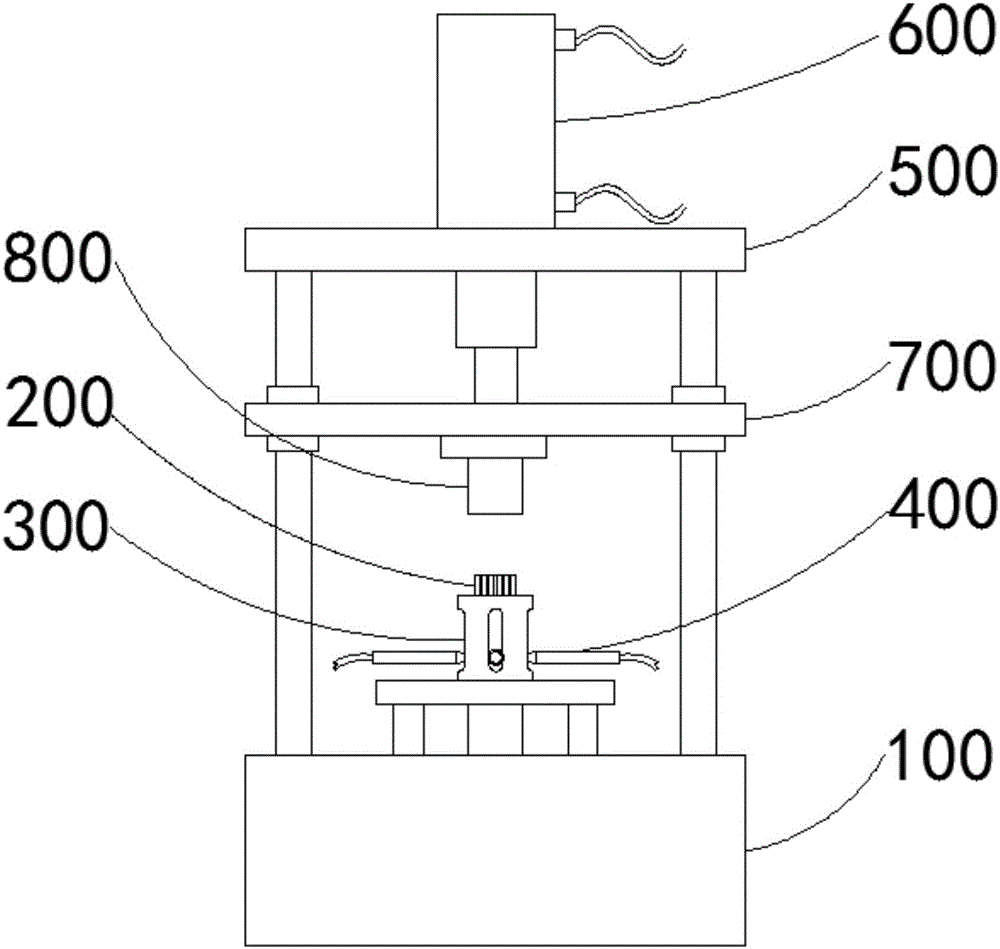
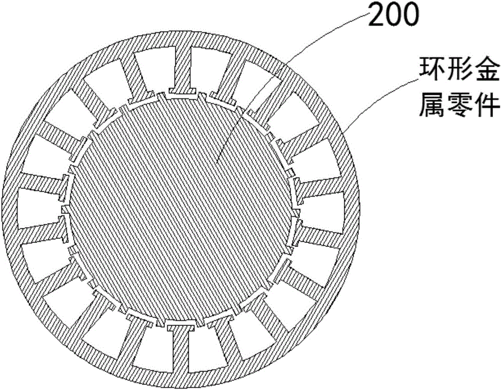
[0037] For the first embodiment, refer to Figure 1-3 , the ring-shaped metal parts welding equipment includes a machine platform 100, the machine platform 100 is provided with a clamping device and a welding device, the clamping device includes a vertically arranged clamping column 200, and the clamping column 200 is cylindrical Shaped and the outer wall is provided with a plurality of clamping strips, a plurality of clamping strips are evenly spaced along the circumferential direction of the clamping column 200, the clamping strips are matched with the clamping grooves on the inner wall of the ring metal part, and the welding device includes multiple Welding torches 400 arranged at uniform intervals along the circumferential direction of the clamping column 200, the length direction of each welding torch 400 is the same as the radial direction of the clamping column 200, and the welding tip of each welding torch 400 is facing the clamping The outer wall of the column 200 . ...

no. 2 example

[0062] The second embodiment, the device provided by the embodiment of the present invention, its realization principle and the technical effect produced are the same as those of the previous embodiment. For brief description, for the parts not mentioned in the device embodiment, please refer to the corresponding content in the previous embodiment .

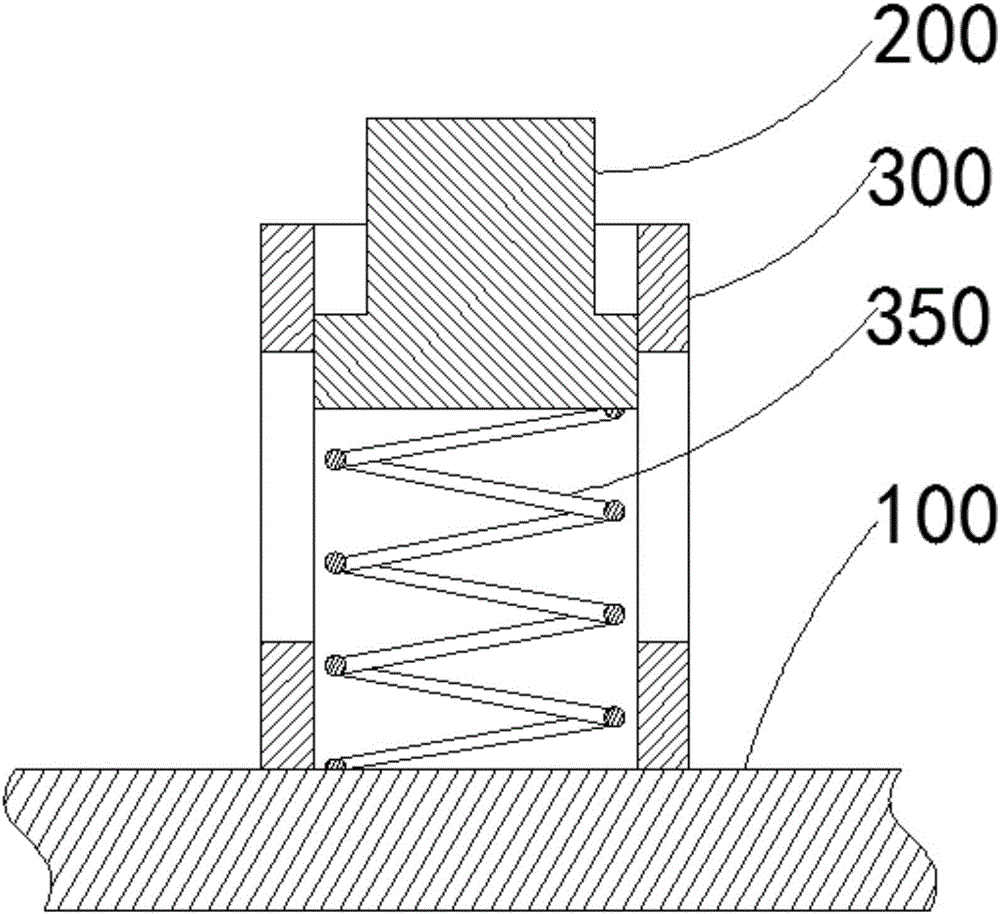
[0063] In this embodiment, a limit sliding bar is provided on the outer wall of the guide column, and a limit slide groove is provided on the inner wall of the sleeve 300 , and the limit slide bar and the limit slide groove match each other.

[0064] Wherein, there are a plurality of limit slide bars, which are evenly spaced along the circumferential direction of the guide column; the number and position of the limit slide grooves correspond to the limit slide bars.

[0065] The purpose of such setting is to prevent the guide column from rotating during the lifting process, thereby improving the stability of its movement.

no. 3 example

[0066] The third embodiment, the implementation principle and technical effect of the device provided by the embodiment of the present invention are the same as those of the previous embodiment. For a brief description, for the parts not mentioned in the device embodiment, please refer to the corresponding content in the previous embodiment .

[0067] In this embodiment, the sleeve 300 is provided with a limit block for placing the guide column to slide out of the sleeve 300 , and the limit block is detachably connected to the top of the sleeve 300 .

[0068] Wherein, the limiting block is in the shape of a cuboid, which is connected to the top of the sleeve 300 by bolts, and part of it blocks the movement path of the guide post, but does not block the movement path of the clamping column 200 and the ring metal part.

[0069] The purpose of setting the limit block is to effectively prevent the clamping column 200 and the guide column from completely detaching from the sleeve 3...


PUM


Abstract

The invention provides welding equipment for ring-shaped metal parts and belongs to the technical field of part processing. The welding equipment comprises a machine station, wherein a clamping device and a welding device are arranged on the machine station; the clamping device comprises a vertically arranged clamping upright column adopting a cylindrical shape, and a plurality of clamping strips are arranged on the outer wall of the clamping upright column, uniformly arranged in the circumferential direction of the clamping upright column at intervals, and matched with clamping grooves in the inner wall of a ring-shaped metal part; the welding device comprises a plurality of welding guns arranged in the radial direction of the clamping upright column and are uniformly arranged in the circumferential direction of the clamping upright column at intervals, and welding nozzles of the welding guns right face the outer wall of the clamping upright column. The welding equipment for the ring-shaped metal parts adopts the plurality of welding guns for simultaneous welding processing, so that not only can the labor intensity of an operator be reduced effectively and the welding processing efficiency be improved, but also the welding effect can be improved greatly and defects in the prior art can be overcome.

Description

technical field [0001] The invention relates to the technical field of parts processing, in particular to welding equipment for ring-shaped metal parts. Background technique [0002] Welding, also known as welding and welding, is a manufacturing process and technology for joining metal or other thermoplastic materials by means of heating, high temperature or high pressure. [0003] In the production process of automobile and motorcycle parts, ring metal parts are often welded in all directions. In the prior art, the above-mentioned welding mostly relies on the operator to weld the circumferential surface of the annular metal part sequentially with the welding tool held by the operator. The operator not only has high labor intensity, but also has low welding efficiency. Contents of the invention [0004] The purpose of the present invention is to provide a ring-shaped metal parts welding equipment to improve the above problems. [0005] The present invention is achieved l...

Claims


Application Information

Patent Timeline
Patent Type & Authority Applications(China)
IPC IPC(8): B23K37/02B23K37/00B23K37/04
CPCB23K37/00B23K37/006B23K37/02B23K37/0461B23K2101/006
Inventor 周启丰
Owner CHONGQING FENGYANG ELECTROMECHANICAL
Why Eureka
Try Eureka