
Production method for rod end joint bearing of high-precision metal basal body

A rod end joint bearing and metal matrix technology, applied in the field of bearings, can solve the problems affecting the overall quality and service life of the bearing, poor self-lubricating quality, deformation of the inner surface of the metal matrix, etc., to improve self-lubricating quality, improve quality, improve The effect of processing technology

Inactive Publication Date: 2015-10-28
欧德客智能转向系统(浙江)有限公司
View PDF5 Cites 3 Cited by
  • Summary
  • Abstract
  • Description
  • Claims
  • Application Information

AI Technical Summary

Problems solved by technology

The metal used in metal matrix rod end joint bearings is copper material. First, press the processed inner ring of the bearing into the metal matrix ring, then process the outer surface of the metal matrix, and finally push it into the outer ring of the bearing. The outer ring is used to adjust the width and tightness (gap). Since the copper material of the metal matrix has good ductility and deformation, it will cause deformation of the inner surface of the metal matrix, forming an uneven gap, and poor self-lubricating quality, which will affect the overall quality and service life of the bearing.

Method used


Image

  • Production method for rod end joint bearing of high-precision metal basal body
  • Production method for rod end joint bearing of high-precision metal basal body
  • Production method for rod end joint bearing of high-precision metal basal body

Examples


Embodiment Construction

[0020] The following will clearly and completely describe the technical solutions in the embodiments of the present invention with reference to the accompanying drawings in the embodiments of the present invention. Obviously, the described embodiments are only some, not all, embodiments of the present invention. All other embodiments obtained by persons of ordinary skill in the art based on the embodiments of the present invention belong to the protection scope of the present invention.

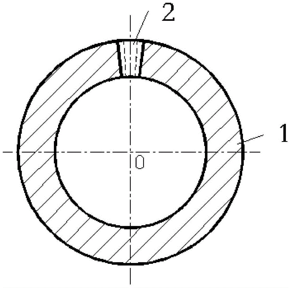
[0021] Such as figure 1 As shown, according to the production method of a high-precision metal matrix rod end joint bearing described in the embodiment of the present invention,

[0022] 1) Machine the inner surface of the inner ring of the bearing with a lathe;

[0023] 2) Machining the outer spherical surface of the inner ring of the bearing with a CNC milling machine;

[0024] 3) Machining the outer ring and rod end of the rod bearing with a lathe;

[0025] 4) Machining the outer surfac...


PUM


Abstract

The invention relates to a production method for a rod end joint bearing of a high-precision metal basal body. The production method comprises the following steps: a lathe and a numerical control milling machine are used for machining the inner surface and the outer spherical surface of an inner ring of the rod end joint bearing; the lathe is used for machining an outer ring of the rod end joint bearing and a rod end; the lathe and the numerical control milling machine are used for machining the outer surface and the inner spherical surface of the metal basal body; a seam is cut by a sawing machine in the axial direction of the metal basal body; and the machined inner ring of the rod end joint bearing is pressed into the metal basal body ring. The production method has the following beneficial effects: the traditional adjustment of the wide tightness (gap) of the rod end joint bearing through machining or other methods is changed to the adjustment of the wide tightness (gap) through cutting one seam with a certain size in the axial direction of the metal basal body and extruding and closing the seam, so that the wide tightness (gap) adjustment controllability is improved, the gap and the error caused by machining and abrasion are made up, the product self-lubrication is improved, the bearing quality is enhanced, and the service life is prolonged; a copper material of the metal basal body is replaced; the machining process is improved; the product quality is improved; the production cost is reduced; and the economic benefit is improved.

Description

technical field [0001] The invention relates to the technical field of bearings, in particular to a production method of a high-precision metal matrix rod end joint bearing. Background technique [0002] Joint bearings are mainly composed of an outer spherical surface of an inner ring and an inner spherical surface of an outer ring, which can withstand large loads. Joint bearings are generally used for low-speed swing motion (that is, angular motion). Since the motion surface is spherical, it can also perform tilting motion (that is, self-aligning motion) within a certain angle range. When the degree is large, it can still work normally, so the self-lubrication of the bearing is particularly important. Rod end joint bearings are a kind of joint bearings. In the production of existing rod end joint bearings, there are PTFE matrix rod end joint bearings and metal matrix rod end joint bearings. The metal used in metal matrix rod end joint bearings is copper material. Firs...

Claims


Application Information

Patent Timeline
IPC IPC(8): B23P15/00
CPCB23P15/003
Inventor 胡建伟卢菊洪朱凌宏李军庆
Owner 欧德客智能转向系统(浙江)有限公司
Learn More