Improved structure of engine oil-gas separator

A technology of oil-gas separator and oil-gas separation chamber, which is applied in the direction of engine components, machines/engines, mechanical equipment, etc., which can solve the problems of inability to meet higher emission limit requirements, complete vehicles that cannot be sold on the market, and bloated layout, etc., to achieve improved Oil and gas separation effect, beneficial to landing, and beneficial to collection

Active Publication Date: 2015-10-28
ANHUI JIANGHUAI AUTOMOBILE GRP CORP LTD
View PDF7 Cites 10 Cited by
  • Summary
  • Abstract
  • Description
  • Claims
  • Application Information

AI Technical Summary

Problems solved by technology

[0008] Existing technologies cannot meet the requirements of higher emission limits, which directly leads to the inability of the entire vehicle to be sold on the market
In order to overcome the above problems, the existing technology meets the emission standards by using the engine cylinder head shield and independent oil and gas separator, which not only leads to complicated pipelines, bloated layout, but also increases the cost too much

Method used


Image

  • Improved structure of engine oil-gas separator
  • Improved structure of engine oil-gas separator
  • Improved structure of engine oil-gas separator

Examples


Embodiment Construction

[0048] The technical solution of the present invention is described in detail below through the examples, and the following examples are only exemplary and can only be used to explain and illustrate the technical solution of the present invention, rather than being interpreted as a limitation to the technical solution of the present invention.

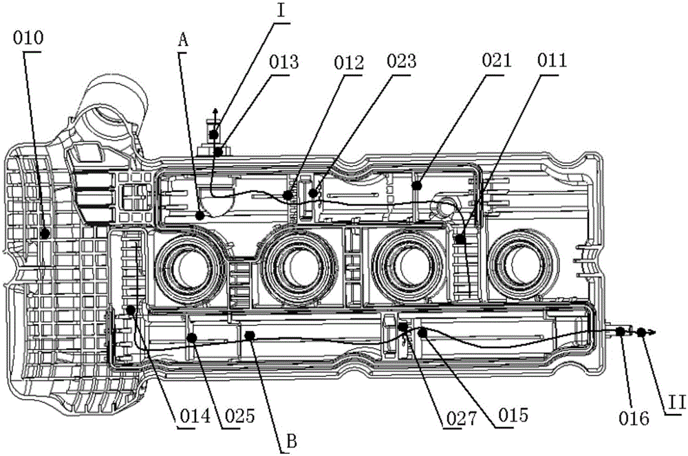
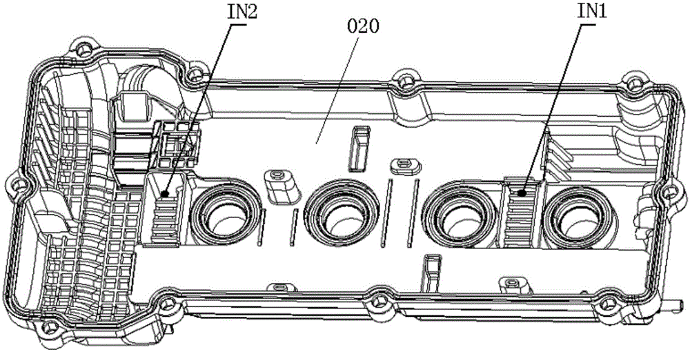
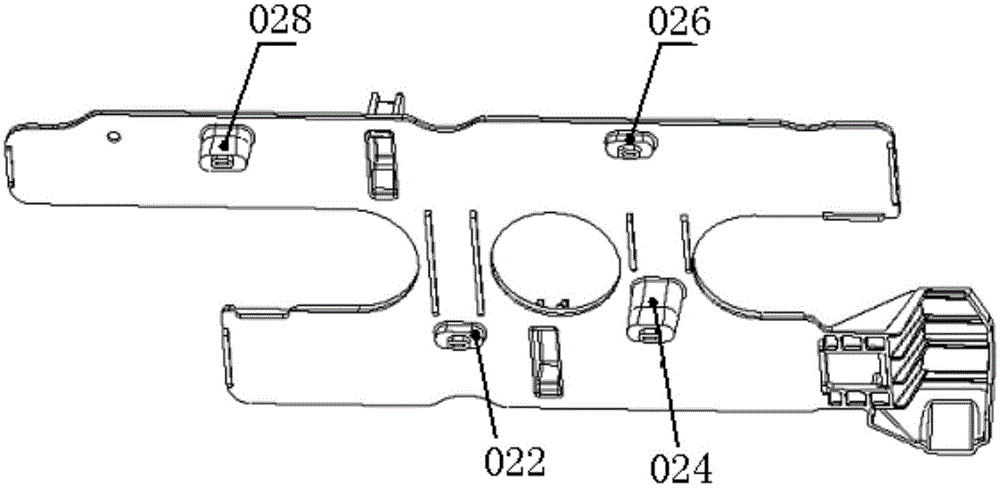
[0049] The invention provides an improved structure of an engine oil-gas separator, such as Figure 6 to Figure 11 As shown, a cylinder head guard 100 is included, and an oil-air separation chamber is arranged on the inner surface of the cylinder head guard 100; the cylinder head guard in this application refers to a cylinder head guard integrated with an oil-gas separator, not Includes cylinder head guards without integrated air separator. In the technical solution of the present application, it is only related to the structure of the oil-air separator on the cylinder head guard, while other structures arranged on the cylinder head gu...


PUM


Abstract

The invention relates to an improved structure of an engine oil-gas separator. The improved structure comprises a cylinder cover shield, wherein oil-gas separating chambers are arranged on the inner surface of the cylinder cover shield; the oil-gas separating chambers comprise the first oil-gas separating chamber positioned on the air suction side and the second oil-gas separating chamber positioned on the air discharge side; the first oil-gas separating chamber adopts a four-stage separating structure; the second oil-gas separating chamber adopts a three-stage separating structure. Through the adoption of the four-stage separating structure and the addition of a cyclone separating plate group structure, when oil-gas mixed gas flows through the cyclone separating plate group, airflow can generate vortex due to the arrangement of a curve plate; as the densities of oil and gas are different, the oil and the gas are separated under the action of the vortex, separated large oil drops directly fall on oil baffles, and separated small oil drops hit against the surfaces of cyclone separating plates and flow towards orifice plates along the surface of the cyclone separating plates, so that the oil-gas separating effect is improved.

Description

technical field [0001] The invention belongs to the technical field of engines, in particular to an improved structure of an engine oil-gas separator. Background technique [0002] During the operation of the engine, a small amount of gas will escape into the crankcase from the gap between the cylinder wall and the piston ring and the gap between the piston and the piston ring, and the blow-by gas will take away the oil on the surface of the piston and cylinder wall, It enters the combustion chamber through the intake system and burns again. But since the oil doesn't burn completely, it can have a negative impact on emissions. The oil must therefore be separated from the blow-by gas in order to comply with emission regulations. [0003] Existing gasoline engines adopt a closed breathing system to meet the requirements of emission regulations. The early engine ventilation system adopts the structure of an external oil-gas separator, which leads to complex pipelines and bloa...

Claims


Application Information

Patent Timeline
Patent Type & Authority Applications(China)
IPC IPC(8): F01M13/04
Inventor 董先瑜张建操张应兵陈园明颜伟刘彤谢有路邱若友倪成鑫
Owner ANHUI JIANGHUAI AUTOMOBILE GRP CORP LTD
Why Eureka
Try Eureka