Inerter capable of adjusting inertance coefficient

A technology of inertial coefficient and inerter, which is applied in the field of vibration-absorbing devices, can solve problems such as difficulty in obtaining vibration-reducing effects, and achieve the effect of simple structure and strong working stability

Inactive Publication Date: 2015-10-28
SHIJIAZHUANG TIEDAO UNIV
View PDF5 Cites 27 Cited by
  • Summary
  • Abstract
  • Description
  • Claims
  • Application Information

AI Technical Summary

Problems solved by technology

However, with the emergence of new liquid materials such as magnetorheological fluids/electrorheological fluids and the increasing advancement of air spring technology, controllable sp

Method used


Image

  • Inerter capable of adjusting inertance coefficient
  • Inerter capable of adjusting inertance coefficient

Examples


Embodiment 1

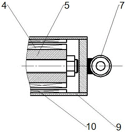
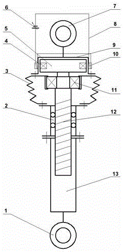
[0032] An inerter with an adjustable coefficient of inertia, the structure of which is as follows figure 1 As shown, it includes upper lifting lug 7, flywheel chamber 9, flywheel 5, leading screw 12, stroke chamber 13, leading screw nut 2, lower lifting lug 1.

[0033] The upper lug 7 is connected with the upper end of the flywheel chamber 9 .

[0034] The periphery of the flywheel chamber 9 is provided with a stator coil 10 electrically connected to the power supply 6 via a wire 8 . The stator coil 10 has an annular structure, and the axis of the stator coil 10 is parallel to the axis of the lead screw 12 . The magnitude and direction of the current generated when the stator coil 10 is energized is controlled by the power supply 6 .

[0035] The flywheel 5 is located in the flywheel chamber 9 , and the periphery of the flywheel 5 is provided with a rotor coil 4 that can rotate with the flywheel 5 . The rotor coil 4 has a ring structure, and the axis of the rotor coil 4 is ...


PUM


Abstract

The invention discloses an inerter capable of adjusting an inertance coefficient. The inerter comprises an upper lifting lug, a flywheel chamber, a flywheel, a lead screw, a stroke chamber, a lead screw nut and a lower lifting lug. The upper lifting lug is connected with the upper end of the flywheel chamber. The flywheel is located inside the flywheel chamber. The upper end of the lead screw is connected with the lower end of the flywheel. The lower end of the lead screw stretches out of the flywheel chamber and extends to the stroke chamber. The lead screw nut is located inside the stroke chamber. The lead screw nut is in screw-thread fit with the lead screw. The lower lifting lug is connected with the lower end of the stroke chamber. The periphery of the flywheel is provided with a rotor coil capable of rotating along with the flywheel. The periphery of the flywheel chamber is provided with a stator coil electrically connected with a power source. Rotation of the flywheel is restrained or accelerated by controlling the magnitude and direction of current generated by the power source, and therefore the inertance coefficient is adjusted to meet the requirement for practical engineering application. The inerter is suitable for being applied on a bridge to achieve the purpose of vibration reduction.

Description

technical field [0001] The invention belongs to the technical field of vibration-absorbing devices, and relates to an inerter, in particular to an inerter with an adjustable inertia coefficient. Background technique [0002] As a mechanical passive element, the inerter solves the single-end problem of the mass element. When a pair of forces act on the two ends of the inerter, the acceleration of the two ends is proportional to the force, and the proportional value is the "inerter coefficient". The new mechanical vibration isolation network composed of "inerter-spring-damper" is widely used in the fields of vehicle suspension vibration isolation, building vibration isolation and high-performance motorcycle steering compensation. [0003] It is a new exploration to use inerters to reduce vibration of bridges. The vibration of bridges is generally caused by environmental excitation and human excitation. Long-span bridges (such as cable-stayed bridges, suspension bridges, etc...

Claims


Application Information

Patent Timeline
IPC IPC(8): F16F15/03F16F15/30E01D19/00
CPCF16F15/03E01D19/00F16F15/30F16F2222/06
Inventor 路永婕张俊宁杨绍普李韶华李双艳王扬李浩玉宋颖
Owner SHIJIAZHUANG TIEDAO UNIV
Why Eureka
Try Eureka