Cage portion and method for the production thereof

A cage and section technology, applied in the direction of rotating parts, bearings, bearing components, etc. that resist centrifugal force, can solve the problem of high manufacturing cost of the cage and achieve the effect of stabilizing the connection structure

Inactive Publication Date: 2015-10-28
SCHAEFFLER TECH AG & CO KG
View PDF5 Cites 2 Cited by
  • Summary
  • Abstract
  • Description
  • Claims
  • Application Information

AI Technical Summary

Problems solved by technology

The manufacturing cost of this cage is very high

Method used


Image

  • Cage portion and method for the production thereof
  • Cage portion and method for the production thereof
  • Cage portion and method for the production thereof

Examples


Embodiment Construction

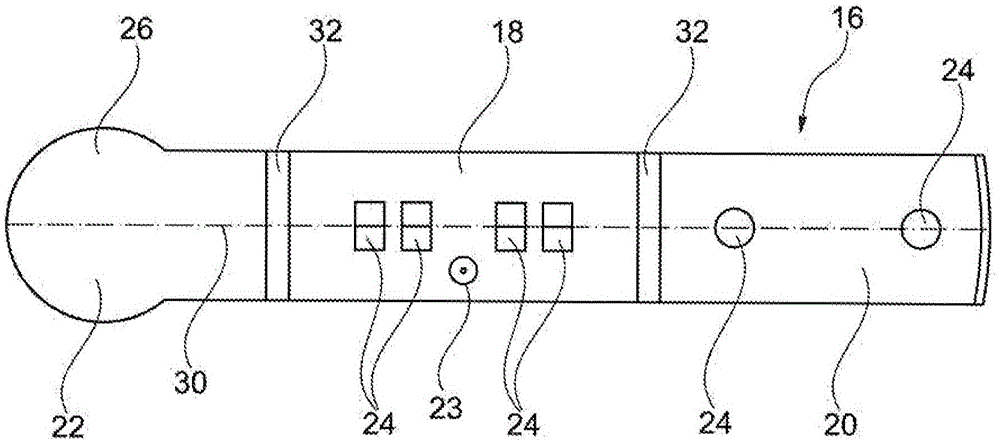
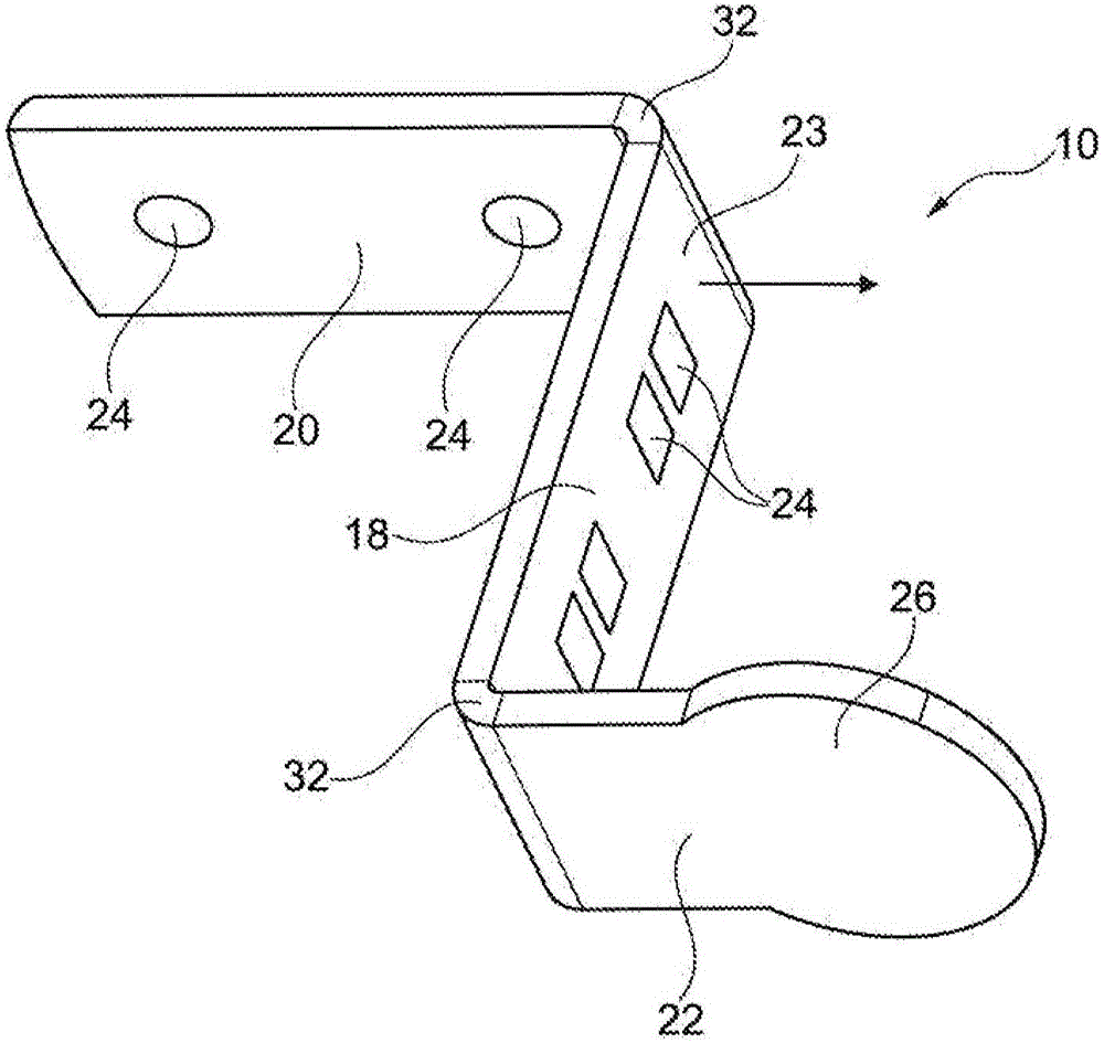
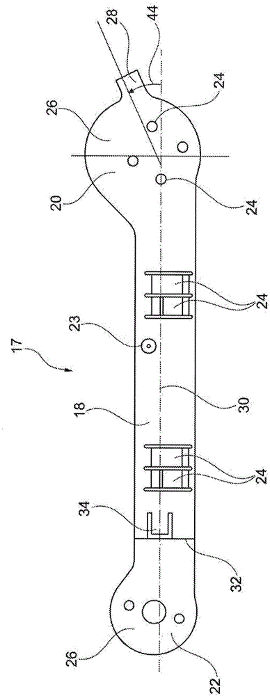
[0031] figure 1 A method for manufacturing a cage part 10 according to a first embodiment is shown (see figure 2 ) has been cut out of the planar plate strip 16. The planar metal strip 16 includes a first leg 20 , a web 18 and a second leg 22 . A transition region 32 to the two arms 20 , 22 is shown on both sides of the web 18 . The longitudinal axis 30 of the planar sheet metal strip 16 is shown in dotted lines. The surface normal is drawn against the sheet plane 23 . The second arm 22 ends in a circular portion 26 , which protrudes beyond the web 18 or the arm 22 by a corresponding width. Furthermore, the lug 18 also has a plurality of crimp-protruding contours 24 with an approximately angular cross-section. The contours 24 are introduced in a continuously alternating manner. Along the longitudinal axis 30 of the web 18 , the contours extend out of the plane of the drawing toward the viewer and inwards of the viewer away from the plane of the drawing in alternating fa...


PUM


Abstract

The invention relates to a cage portion (36), particularly for a meander-shaped cage (12) of a rolling contact bearing (14, 15), comprising at least one cage part (10, 11, 11') made of a Z-shaped bent sheet-metal strip (16, 17) with a first arm (20), a web (18) and a second arm (22), wherein the first arm (20) and the second arm (22) are bent substantially perpendicularly to the sheet metal plane (23). The invention further relates to a method for producing a cage portion (36), particularly for a meander-shaped cage (12) of a rolling contact bearing (14, 15).

Description

technical field [0001] The invention relates to a cage segment for a rolling bearing, in particular a meander-shaped cage, and to a method for producing such a cage segment. Cage segments are especially suitable for forming segmented cages of roller bearings. Background technique [0002] Usually, the rolling elements of larger rolling bearings are held and guided in cages in order to avoid jamming of the rolling elements, for example by supporting one another. Typically, the rollers of larger roller bearings, eg cylindrical roller bearings or tapered roller bearings, are guided by cages. [0003] A cage for a rolling bearing is known from DE 424 712 A, which encloses and guides the rollers of the rolling bearing individually. The cage is produced from a solid material by machining, whereby the production of the cage is expensive and the material expenditure is high. This disadvantageously leads to high manufacturing costs. [0004] A one-piece cage for roller bearings c...

Claims


Application Information

Patent Timeline
Patent Type & Authority Applications(China)
IPC IPC(8): F16C33/54F16C33/50
CPCF16C33/50F16C33/548F16C19/26F16C2300/14
Inventor 霍斯特·马祖赫赫尔曼·盖尔米歇尔·贝努茨
Owner SCHAEFFLER TECH AG & CO KG
Why Eureka
Try Eureka