Lead ingot slicer

A slicer and lead ingot technology, which is applied in the field of lead ingot slicers, can solve the problems of low service life and high production cost, and achieve the effects of small wear, improved production efficiency, and reduced costs

Inactive Publication Date: 2015-11-04
ANHUI AULY MACHINERY TECH
View PDF6 Cites 0 Cited by
  • Summary
  • Abstract
  • Description
  • Claims
  • Application Information

AI Technical Summary

Problems solved by technology

[0003] The purpose of the present invention is to provide a novel lead ingot slicer in order to solve the defects of the existing lead ingot slicer with low service life and high production cost

Method used


Image

  • Lead ingot slicer
  • Lead ingot slicer
  • Lead ingot slicer

Examples


Embodiment Construction

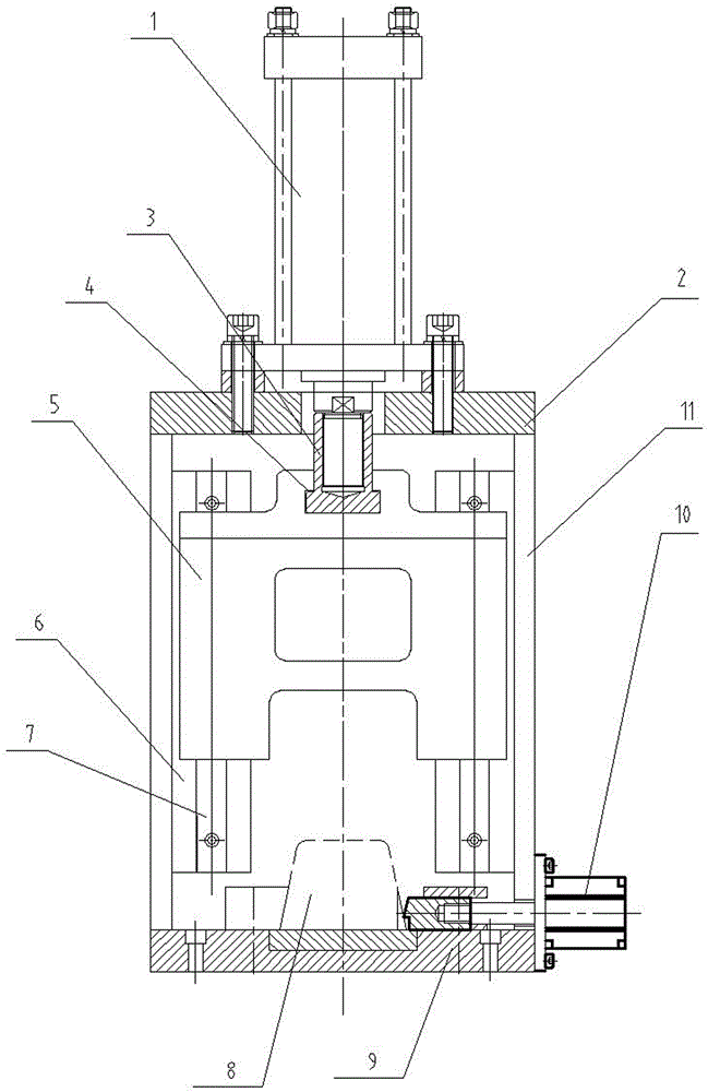
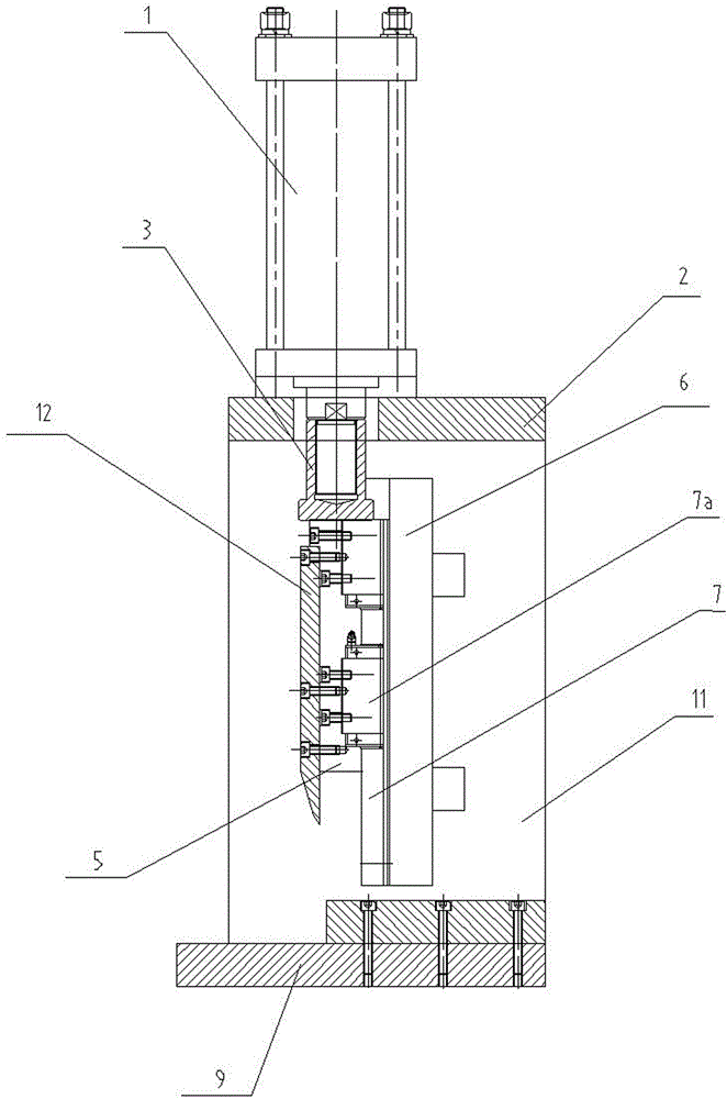
[0012] like figure 1 As shown, the lead ingot slicing machine provided by the present invention comprises a frame made up of an upper plate 2, a lower plate 9 and vertical plates 11 connected on both sides, an oil cylinder 1 is arranged on the upper plate 2, and the piston rod of the oil cylinder 1 is connected A T-shaped connector 3, the T-shaped connector 3 is connected with the T-shaped hole 4 on the cutter frame 5 upper end. like image 3 As shown, the cutter 12 is connected to the cutter frame 5. This connection makes the cutter frame and the piston rod of the oil cylinder have the advantages of simple structure and high connection strength, which plays a great role in improving the service life.

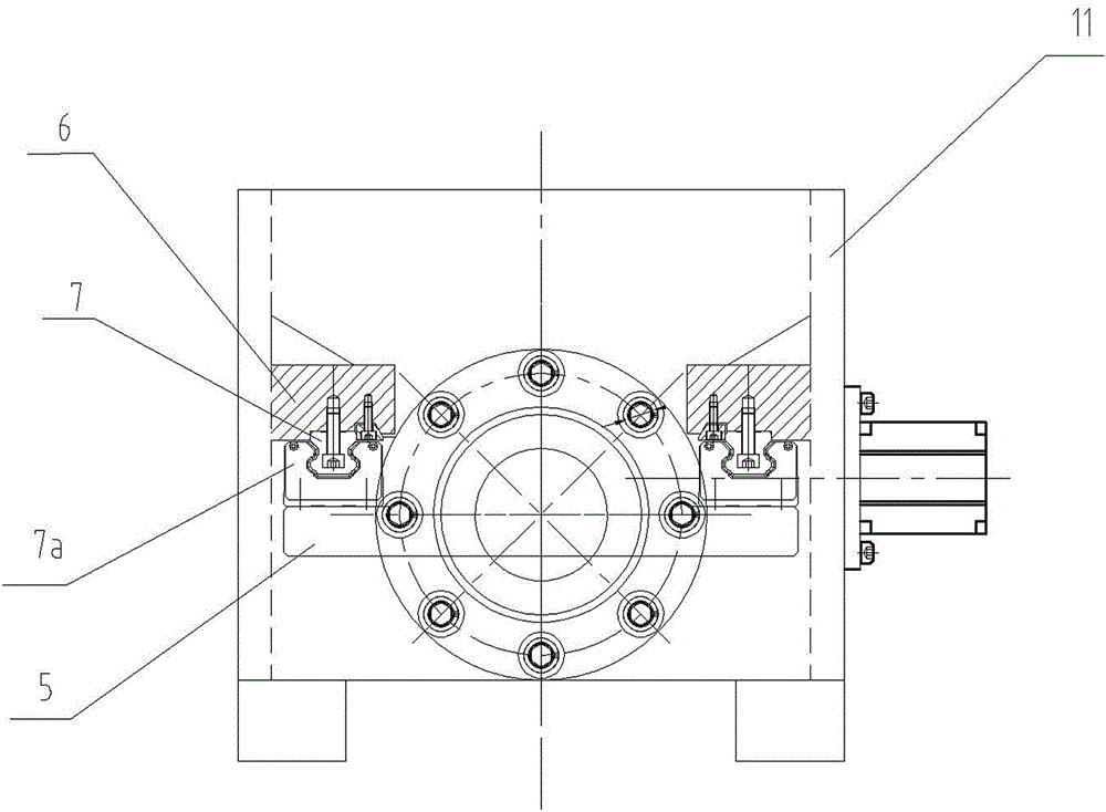
[0013] like figure 1 , figure 2 and image 3 As shown, a guide rail base 6 is respectively connected to the inner side of the vertical plate on both sides of the frame, and each guide rail base 6 is provided with a linear guide rail 7, and the linear guide rail 7 is provid...


PUM


Abstract

The invention relates to a lead ingot slicer used in a lead ingot granulation device. The lead ingot slicer comprises a rack composed of an upper plate (2), a lower plate (9) and stand plates (11) connected to the two sides. An oil cylinder (1) is arranged on the upper plate (2). A piston rod of the oil cylinder (1) is connected with a T-shaped connector (3). The T-shaped connector (3) is connected and matched with a T-shaped hole in the upper end of a cutter rest (5). A cutter (12) is connected to the cutter rest. The stand plates on the two sides of the rack are each connected with a guide rail base (6). A linear guide rail (7) and a sliding base (7a) of the linear guide rail (7) are arranged on each guide rail base (6). Each sliding base (7a) is connected with the cutter rest (5). The lead ingot slicer has the beneficial effects that due to the fact that the standard linear guide rails capable of being purchased on the market are adopted, manufacturing cost is obviously reduced, and abrasion to the linear guide rails is small; and production efficiency is improved, the service life of the cutter is prolonged, and cost is reduced.

Description

technical field [0001] The invention relates to a lead ingot granulation equipment, in particular to a lead ingot slicer. Background technique [0002] The lead pellet slicer is an important equipment for cutting lead lumps in the lead ingot granulator. It cuts the lead pellets into flakes or strips, and the strip-shaped lead flakes are then sent to the lead pellet granulator to make granular lead pellets. . In the existing slicing machine, the cutter frame slides up and down in cooperation with the dovetail guide rail arranged on the frame, and the cutter frame and the cutter on it are driven by an oil cylinder to cut off the lead ingot. Due to the large force during the slicing operation, the dovetail guide rail is severely worn and the gap is large, and the corresponding knife operation is unstable, and the knife is prone to chipping. Therefore, its service life is low and its production cost is high. Invention content: [0003] The purpose of the present invention i...

Claims


Application Information

Patent Timeline
Patent Type & Authority Applications(China)
IPC IPC(8): B22F9/04
Inventor 王磊吕紫玲
Owner ANHUI AULY MACHINERY TECH
Why Eureka
Try Eureka