On-line Density Detection Structure of Mixed Drilling Fluid

A detection structure and density detection technology, which is applied in earthwork drilling, wellbore flushing, wellbore/well components, etc., can solve the problems of wasting drilling fluid materials, incorrectly sensing pressure, and failing to detect density, etc., and achieve saving The effect of density detection time, guaranteed sealing performance, and limited space saving

Active Publication Date: 2018-06-19
CHONGQING UNIVERSITY OF SCIENCE AND TECHNOLOGY
View PDF5 Cites 0 Cited by
  • Summary
  • Abstract
  • Description
  • Claims
  • Application Information

AI Technical Summary

Problems solved by technology

[0003] The density detection device currently used is a general density meter installed in the drilling fluid tank to detect the density. This detection method needs to wait until the mixed drilling fluid in the drilling fluid tank is immersed in the sensor of the density meter to detect the density, which is lagging behind. To adjust the density once, the residual drilling fluid in the drilling fluid tank must be emptied to detect the adjusted density, which wastes drilling fluid materials. When manually testing the density, it is necessary to take samples from the drilling fluid tank. The action is dangerous and does not meet the requirements of safe operation.
In addition, the original density meter installation scheme is relatively cumbersome. It is necessary to install the original drilling fluid tank after opening the hole.
[0004] When the existing general density meter detects the density of the fluid flowing into the vertical pipeline in the forward direction (from top to bottom), when the fluid flow rate is too high, a static pressure negative pressure zone will be generated at the elbow joint at the inlet of the density detection pipeline, and the negative pressure zone will If the upper pressure sensor is involved, the pressure cannot be correctly sensed, which directly affects the accuracy of the density meter reading. Currently, vertical pipelines are tested by inversion, and the fluid flows into the density detection pipeline from the bottom up. When the fluid pressure is low, the fluid cannot immerse the pressure sensor. , the density cannot be detected

Method used


Image

  • On-line Density Detection Structure of Mixed Drilling Fluid
  • On-line Density Detection Structure of Mixed Drilling Fluid
  • On-line Density Detection Structure of Mixed Drilling Fluid

Examples


Embodiment Construction

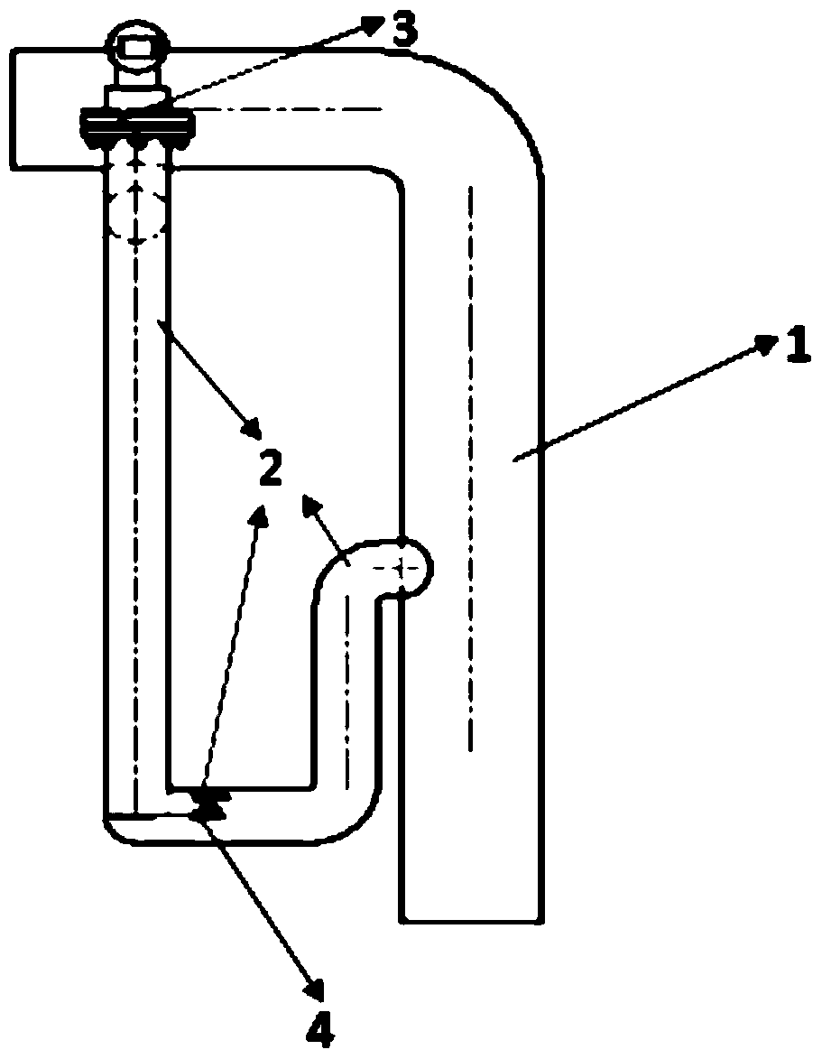
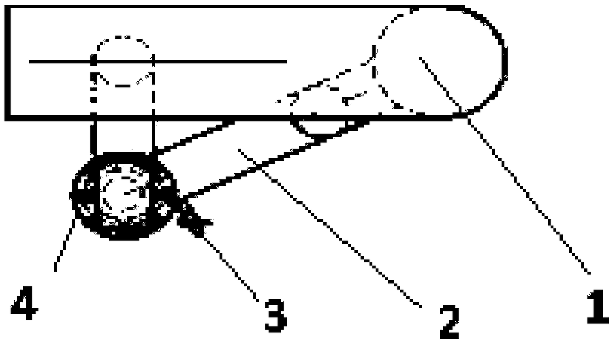
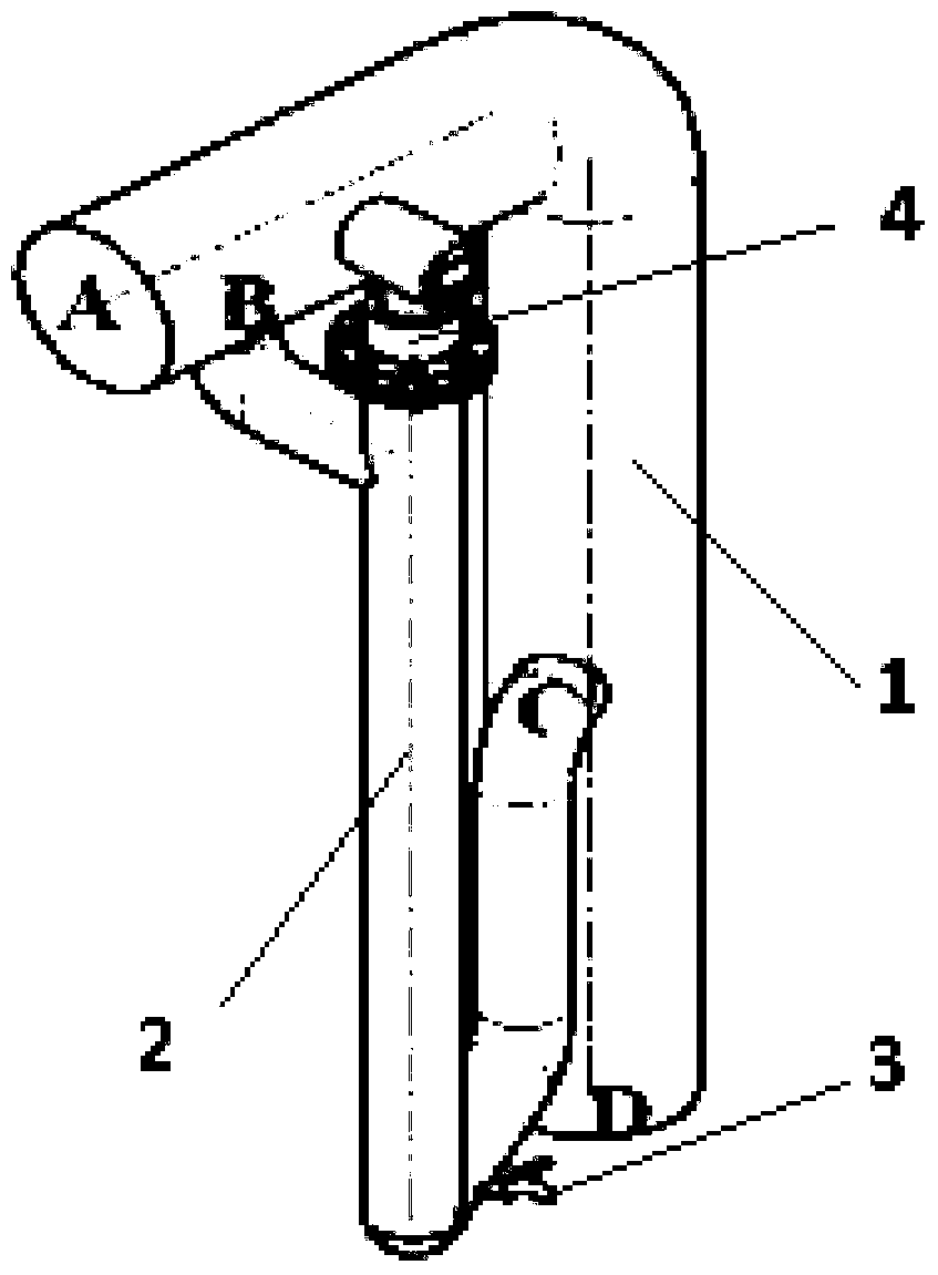
[0026] see Figure 1a to Figure 1c , is a preferred embodiment of the mixed drilling fluid online density detection structure, including an inverted L-shaped main pipeline 1 of the mixed drilling fluid. The main pipeline 1 includes a horizontal main pipeline 1, a vertical main pipeline 1, and also includes A U-shaped density detection pipeline 2 and a differential pressure density meter 3, the density detection pipeline 2 includes a first vertical pipe, a second vertical pipe and a connecting pipe connected between the lower ends of the first vertical pipe and the second vertical pipe , the length of the first vertical pipe is greater than the length of the second vertical pipe, the upper end of the first vertical pipe communicates with the horizontal main pipe 1 through the connecting pipe, and the second vertical pipe communicates with the vertical main pipe 1 through the connecting pipe , forming a one-piece structure. The differential pressure density meter 3 is installed...


PUM


Abstract

The invention discloses a mixed drilling fluid online density detection structure, which comprises an inverted L-shaped main pipeline of the mixed drilling fluid, the main pipeline includes a horizontal main pipeline, a vertical main pipeline, and a U-shaped density detection pipeline, For a differential pressure density meter, the density detection pipeline includes a first vertical pipe, a second vertical pipe, and a connecting pipe connected between the lower ends of the first vertical pipe and the second vertical pipe, and the length of the first vertical pipe is longer than that of the second vertical pipe. The length of two vertical pipes, the upper end of the first vertical pipe communicates with the horizontal main pipeline, the second vertical pipe communicates with the vertical main pipeline, and the differential pressure density meter is installed on the density detection pipeline. It has a simple structure and can instantly and accurately detect the density of the mixed drilling fluid flowing forward in the main pipeline.

Description

technical field [0001] The invention belongs to the technical field of drilling equipment and relates to a structure for detecting the online density of mixed drilling fluid. Background technique [0002] Compared with land and shallow sea drilling, the environment of deep sea drilling is more complicated, and the technology adopted is different from that of land. In many areas, there are narrow drilling fluid density windows, shallow gas, and shallow water. It is difficult to control the formation pressure, and it is very easy to It will cause overflow and other downhole complex situations, and in severe cases, it will lead to blowout and well leakage accidents, which will cause great difficulties to drilling. In order to control hazards such as shallow water flow, it is necessary to use a dynamic well killing system. Slurry device, which automatically adjusts to the required drilling fluid density, directly supplies the mud pump to continuously pump downhole into the well...

Claims


Application Information

Patent Timeline
Patent Type & Authority Patents(China)
IPC IPC(8): E21B21/00G01N9/26
Inventor 雷宗明赵士林王冬平黄靖富蔡文涛
Owner CHONGQING UNIVERSITY OF SCIENCE AND TECHNOLOGY
Why Eureka
Try Eureka