Pipe connecting structure

A technology of connecting pipe structure and round pipe, which is applied in the direction of pipe/pipe joint/fitting, sealing surface connection, pipe heating/cooling, etc. It can solve the problems of troublesome flange welding and disassembly, a lot of time for disassembly, waste of labor costs, etc. Easy to fall off, not easy to fall off, easy to disassemble

Inactive Publication Date: 2015-11-04
CHENGDU MATSUKAWA METAL MATERIALS
View PDF7 Cites 1 Cited by
  • Summary
  • Abstract
  • Description
  • Claims
  • Application Information

AI Technical Summary

Problems solved by technology

[0002] In the existing construction site, traditional methods are often used for water supply or other fluid pipelines, such as arranging steel wires outside the pipelines for binding and winding, or using flanges for butt welding to weld the two pipelines to death, but this operation method not only Time-consuming and labor-intensive, requiring a lot of labor costs
Moreover, when the engineering process is fast, the pipeline needs to be relocated. At this time, it takes a lot of time to disassemble and reassemble the pipeline. The disassembly of the flange welding form is more troublesome, and even more cost is required to purchase a new flange.

Method used


Image

  • Pipe connecting structure
  • Pipe connecting structure

Examples


Embodiment Construction

[0016] The present invention will be further described below in conjunction with the accompanying drawings and specific embodiments.

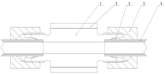
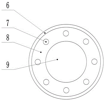
[0017] Such as figure 1 , figure 2 As shown, a connecting pipe structure includes a joint 1 provided with a fluid channel, a round pipe 4 connected with the fluid channel, and ferrules arranged at both ends of the joint 1; the inner end faces of the two ends of the joint 1 are tapered surfaces, and the outer end faces There are external threads; the ferrule is formed by welding the lock nut 3 and the clamp 2, and there is a gap between the lock nut 3 and the clamp 2 to be inserted into the port of the joint 1; the size of the lock nut 3 Adapted to the diameter of the outer end surface of the joint 1, and has an internal thread that engages with the external thread of the outer end surface of the joint 1; the clamp 2 is arranged between the lock nut 3 and the joint 1, and is in the middle of the clamp 2 An intubation through hole adapted to t...


PUM


Abstract

The invention discloses a pipe connecting structure which comprises a connector provided with a fluid channel, round pipes in butting connection with the fluid channel, and clamping sleeves arranged at the two ends of the connector. The inner end faces the two ends of the connector are each a conical face, and the outer end faces of the two ends of the connector are each provided with an external thread. Each clamping sleeve is formed by welding a lock nut and a clamping device, and a gap is reserved between each lock nut and the corresponding clamping device and used for containing the port of the connector in a sleeving mode. The size of each lock nut is matched with the diameter of the outer end face of the connector, and the middle of each clamping device is provided with an internal thread engaged with the external thread on the outer end face of the connector. The clamping devices are arranged between the lock nuts and the connector, and pipe inserting through holes matched with the round pipes in diameter are formed in the middles of the clamping devices. The ends, facing the connector, of the clamping devices are also conical faces. The axial included angle of the conical face of the connector is larger than that of the conical face of each clamping device. By means of the pipe connecting structure, rapid pipe connection can be achieved.

Description

technical field [0001] The invention relates to the field of pipeline engineering, in particular to a connecting pipe structure. Background technique [0002] In the existing construction site, traditional methods are often used for water supply or other fluid pipelines, such as arranging steel wires outside the pipelines for binding and winding, or using flanges for butt welding to weld the two pipelines to death, but this operation method not only It is time-consuming and labor-intensive, and a lot of labor costs are wasted. Moreover, when the engineering process is fast, the pipeline needs to be relocated. At this time, it takes a lot of time to disassemble and reassemble the pipeline. The disassembly of the flange welding form is more troublesome, and even the cost of purchasing a new flange needs to be increased. Contents of the invention [0003] The present invention aims to provide a connection structure to solve the above problems. [0004] To achieve the above ...

Claims


Application Information

Patent Timeline
Patent Type & Authority Applications(China)
IPC IPC(8): F16L19/065F16L19/08F16L53/00
CPCF16L19/0653F16L19/08F16L53/38
Inventor 周建川
Owner CHENGDU MATSUKAWA METAL MATERIALS
Why Eureka
Try Eureka