Ball placement detection equipment and application thereof

A testing equipment and ball-planting technology, which is applied in the direction of optical testing for flaws/defects, can solve the problems of misjudgment, time-consuming, and unfavorable implementation of light-sensing sensors, and achieves simple installation and adjustment, simple and accurate operation, and easy implementation. Effect

Inactive Publication Date: 2015-11-04
SHANGHAI WEISONG IND AUTOMATION
View PDF8 Cites 5 Cited by
  • Summary
  • Abstract
  • Description
  • Claims
  • Application Information

AI Technical Summary

Problems solved by technology

[0004] (1) The detection of solder ball picking defects needs to be scanned multiple times by column or row, which is time-consuming;
[0005] (2) Each time a column or row is detected, it can only be determined that this column or row has defects in solder ball picking, and it is impossible to further know how many defects there are in this column or row;
[0006] (3) The detection of solder ball placement defects requires the design of complex optical paths and the use of devices such as glass with a specific refractive index, which is sensitive to parts processing and installation accuracy, which is not conducive to specific implementation;
[0007] (4) Fine debris such as dust in the air may change the refraction and reflection of light, resulting in the light not being transmitted according to the ideal optical path, causing the light sensor to make a misjudgment

Method used


Image

  • Ball placement detection equipment and application thereof
  • Ball placement detection equipment and application thereof
  • Ball placement detection equipment and application thereof

Examples


Embodiment 1

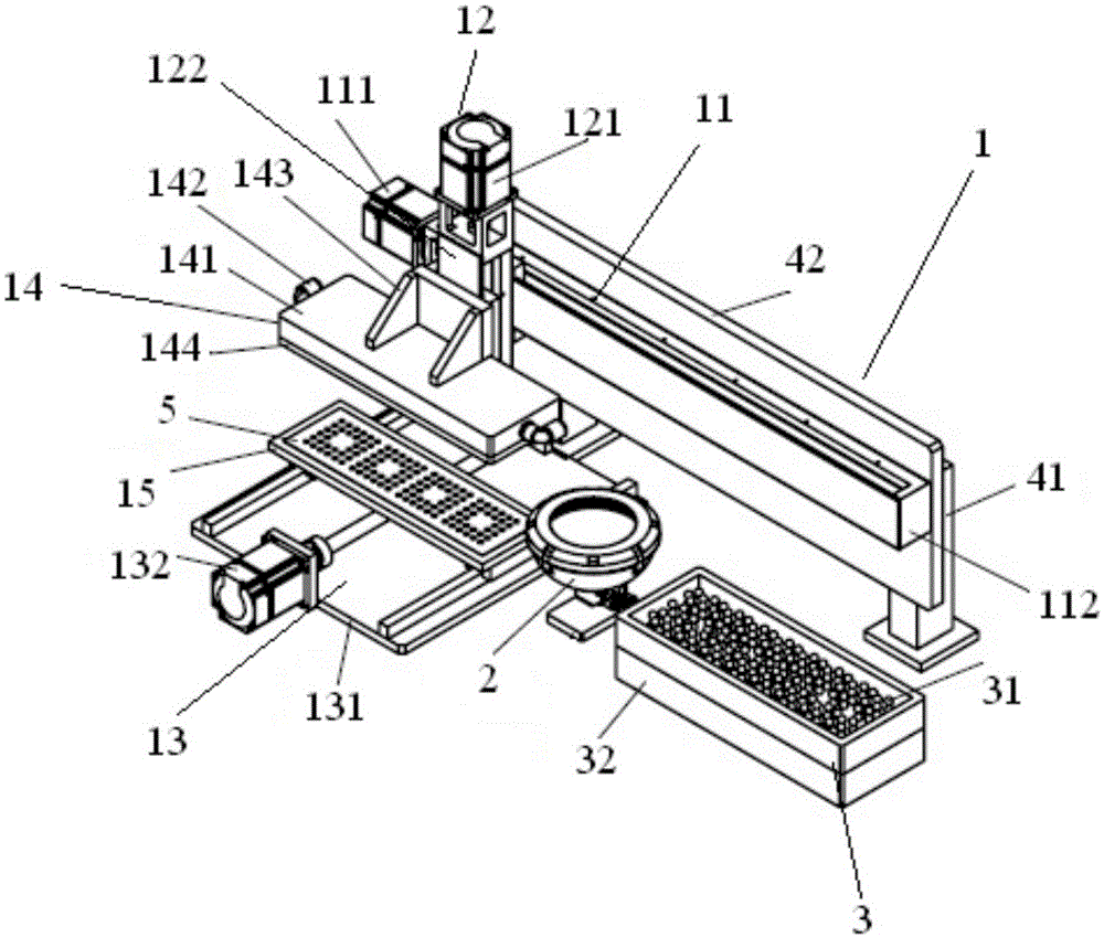
[0067] A kind of implant detection equipment, its structure is as follows: figure 1 As shown, the testing equipment is set on a platform, and the testing equipment includes a ball planting unit 1, a testing unit 2 and a ball supplying unit.

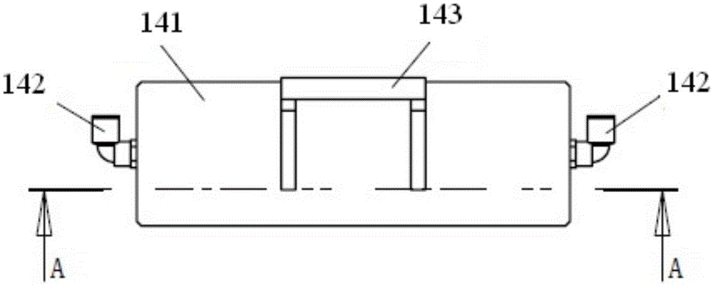
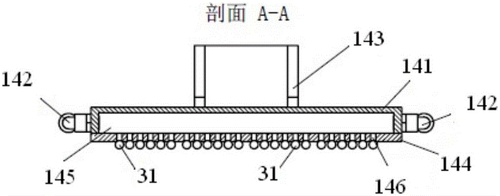
[0068] The ball planting unit 1 comprises a conveying device, and a ball planting device 14 and a substrate placing platform 15 arranged on the conveying device, the substrate placing platform 15 is provided with a substrate 5, and the conveying device is formed along the directions of the X axis, the Y axis and the Z axis respectively. The moving X-direction conveying device 11, the Y-direction conveying device 12 and the Z-direction conveying device 13 are composed;

[0069] The X-direction transmission device 11 is arranged on the supporting device 4 fixed on the stand, and the X-direction transmission device 11 includes an X-direction controller 111 and an X-direction transmission plate 112 arranged on the support device, and the X-di...

Embodiment 2

[0080] The application of the ball planting detection equipment as described in embodiment 1 may further comprise the steps:

[0081] (a) Solder ball pickup

[0082] Adjust the X-direction controller 111 to control the Y-direction transfer device 12 equipped with the ball planting device 14 to move to the top of the ball supply unit 3 along the X-axis direction, and then adjust the Y-direction controller 121 to control the ball planting device 14 to descend along the Y-axis direction To pick up the height of the solder ball, turn on the vacuum generator, absorb the solder ball 31 from the ball supply unit 3, and then adjust the Y direction controller 121 to control the ball planting device 14 to rise to the initial height along the Y axis;

[0083] (b) Solder ball pickup defect detection

[0084] Adjust the X-direction controller 111 to control the ball planting device 14 that has absorbed the solder ball 31 to move to the top of the detection unit 2 along the X-axis directio...


PUM


Abstract

The invention relates to ball placement detection equipment and its application. The detection equipment is arranged on a stand. The detection equipment comprises a ball placement unit (1), a detection unit (2) and a ball feeding unit (3). The ball placement unit (1) comprises a conveyer, a ball placement device (14) and a substrate placement platform (15), wherein the ball placement device and the substrate placement platform are arranged on the conveyer. A substrate (5) is arranged on the substrate placement platform (15). The detection unit (2) contains a fixed plate (21), an image sensor (22) disposed on the fixed plate (21) and a light source (24) mounted above the image sensor (22). A polariscope (23) is arranged between the image sensor (22) and the light source (24). The image sensor (22) and a PLC are connected. The ball feeding unit (3) is composed of a ball feeding box (32) and solder balls (31) placed inside the ball feeding box (32). In comparison with the prior art, the invention has the following advantages: the ball placement detection equipment is simple to operate; detection results are accurate; and a large area of defects are convenient to find.

Description

technical field [0001] The invention relates to a detection device, in particular to a implant detection device and its application. Background technique [0002] Ball planting is a key step in the molding stage of packages such as BGA (Ball Grid Array), CSP (Chip Size Package) and WLP (Wafer Level Package). During the ball planting process, the pick-up and placement of solder balls affect the final ball planting results. Therefore, solder ball pick-up defects and solder ball placement defects need to be identified and judged to improve the final ball planting quality. For example, U.S. Patent No. 5,615,823 discloses a detection method for solder ball pick-up defects and solder ball placement defects: a through-beam laser sensor is used to detect solder ball pick-up defects, and an optical sensor is used to detect solder ball placement defects. Due to the small diameter of the solder ball, the rays of the through-beam laser sensor need to be very thin, i.e. at the μm level...

Claims


Application Information

Patent Timeline
Patent Type & Authority Applications(China)
IPC IPC(8): G01N21/88
Inventor 刘劲松钟亮毕秋吉
Owner SHANGHAI WEISONG IND AUTOMATION
Why Eureka
Try Eureka