
Sub-synchronous oscillation suppression method based on modal damping current injection

A sub-synchronous oscillation and damping current technology, applied in the direction of reducing/preventing power oscillation, electrical components, control systems, etc., can solve the problems of sub-synchronous or super-synchronous current utilization reduction, reduced STATCOM suppression ability, and no consideration of shunt effects, etc. , to achieve the effect of improving the system sub-synchronous stability, suppressing sub-synchronous oscillation, and high output current utilization

Inactive Publication Date: 2015-11-04
NORTH CHINA ELECTRIC POWER UNIV (BAODING)
View PDF2 Cites 7 Cited by
  • Summary
  • Abstract
  • Description
  • Claims
  • Application Information

AI Technical Summary

Problems solved by technology

However, the existing subsynchronous damping control strategy does not consider the different shunting effect of the actual system on the subsynchronous current and supersynchronous current, so that the output subsynchronous current and supersynchronous current of STATCOM are basically equal, resulting in the subsynchronous or supersynchronous current of STATCOM output. The utilization rate of synchronous current is reduced, and the suppression ability of STATCOM is reduced under the same capacity

Method used


Image

  • Sub-synchronous oscillation suppression method based on modal damping current injection
  • Sub-synchronous oscillation suppression method based on modal damping current injection
  • Sub-synchronous oscillation suppression method based on modal damping current injection

Examples


specific Embodiment approach

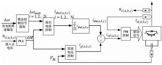
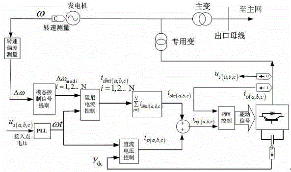
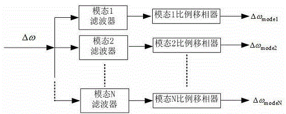
[0033] attached figure 2 It is a schematic diagram of the specific implementation of the subsynchronous oscillation suppression method based on modal damping current injection for synchronous generators. This method extracts the subsynchronous modal signal in the generator speed deviation signal and the voltage of the DC capacitor of the full-control inverter Deviation, the sub-synchronous or super-synchronous damping current command signal used to suppress sub-synchronous oscillation and the fundamental active current command signal to maintain the DC voltage stability of the fully-controlled inverter are obtained through the damping current control link and the DC voltage voltage control link, attached image 3 is the specific implementation of the modal signal extraction link, Figure 4 is the specific implementation of the damping current control link, Figure 5 It is the specific implementation of the DC voltage control link; through PWM control, the output current of ...


PUM


Abstract

The invention discloses a sub-synchronous oscillation suppression method based on modal damping current injection, which belongs to the field of power system stabilization and control. The sub-synchronous oscillation suppression method comprises the steps that: sub-synchronous modal signals in a power generator rotation speed deviation signal and a voltage deviation value of a DC capacitor of a fully controlled type inverter are extracted, and sub-synchronous or super-synchronous damping current command signals for suppressing sub-synchronous oscillation as well as fundamental wave active current command signals for maintaining stability of a DC voltage of the fully controlled type inverter are acquired through a damping current control link and a DC voltage control link; an output current of the fully controlled type inverter tracks the current command signals through PWM control, and the output current is injected into a power generator set to generate electromagnetic torque of damping sub-synchronous oscillation, thereby achieving the purpose of suppressing sub-synchronous oscillation. The sub-synchronous oscillation suppression method based on modal damping current injection is fast in response speed, high in utilization rate of the output current of the inverter, can combine a plurality of sub-synchronous torsional oscillation modes, improves sub-synchronous stability of the system, and reduces torsional oscillation fatigue damages to a shaft system of a large-scale power generator.

Description

technical field [0001] The invention belongs to the field of power system stability and control, in particular to a subsynchronous oscillation suppression method based on modal damping current injection. Background technique [0002] Fixed Series Capacitor Compensation (FSC) and High Voltage Direct Current (HVDC) are economical and effective measures to improve power system transmission capacity and stability. However, the fixed series capacitor compensation will cause the subsynchronous resonance (SSR) of the generator set, and the HVDC will interact with the generator set closer to it to generate subsynchronous oscillation (SSO), both of which may cause power generation The shafting of the unit is fatigued and may even cause the shafting to break. In my country, large-capacity, long-distance, and cross-regional power transmission has become an inevitable trend in the development of power systems. With the increase in the number of series capacitor compensators in transmi...

Claims


Application Information

Patent Timeline
Patent Type & Authority Applications(China)
IPC IPC(8): H02J3/24H02P9/00
Inventor 肖湘宁罗超张剑陈鹏伟
Owner NORTH CHINA ELECTRIC POWER UNIV (BAODING)
Learn More