Method for improving wire dropping of punching dielectric layer of light bar plate

A technology of light strips and dielectric layers, which is applied in the processing of insulating substrates/layers, mechanical/acoustic circuit processing, electrical components, etc., can solve the problems of light strips that are easy to lose wires, and reduce the risk of crushing and scrapping. , The problem of wire loss is improved, and the effect of increasing hardness

Active Publication Date: 2015-11-04
KINWONG ELECTRONICS TECH LONGCHUAN
View PDF5 Cites 2 Cited by
  • Summary
  • Abstract
  • Description
  • Claims
  • Application Information

AI Technical Summary

Problems solved by technology

[0004] In view of the above-mentioned deficiencies in the prior art, the purpose of the present invention is to provide a method for improving the wire loss of the medium layer of the lamp strip board, aiming to solve the problem that the light strip board is easy to lose wire during the punching process in the prior art

Method used


Image

  • Method for improving wire dropping of punching dielectric layer of light bar plate
  • Method for improving wire dropping of punching dielectric layer of light bar plate

Examples


Embodiment Construction

[0021] The present invention provides a method for improving the thread loss of the medium layer of the punching plate of the lamp strip. In order to make the purpose, technical solution and effect of the present invention clearer and clearer, the present invention will be further described in detail below. It should be understood that the specific embodiments described here are only used to explain the present invention, not to limit the present invention.

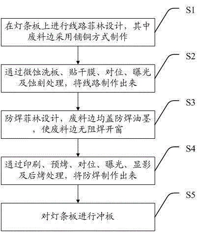
[0022] see figure 1 , figure 1 It is a flow chart of a preferred embodiment of a method for improving the wire drop of the medium layer of the light bar plate punching plate provided by the present invention, which includes steps:

[0023] S1. Carry out circuit film design on the light strip, and the waste side is made by copper laying;

[0024] S2. Make the circuit through micro-etching to wash the board, paste dry film, alignment, exposure and etching;

[0025] S3, Solder-proof film design, the waste material is cove...


PUM


Abstract

The invention discloses a method for improving the wire dropping of a punching dielectric layer of a light bar plate, and the method comprises the steps: A, carrying out circuit film design on the light bar plate, wherein a waste edge is prepared in a mode of copper laying; B, enabling a circuit to be manufactured through miniature etching and washing of the plate, dry film pasting, alignment, exposure and etching; C, carrying out solder mask film design, enabling the waste edge to be covered by solder mask ink, and enabling the waste edge to achieve windowing without soldering resistance; E, manufacturing a solder mask through printing, pre-baking, alignment, exposure, development, and post-baking; F, carrying out the punching of the light bar plate. According to the invention, the circuit waste edge is manufactured in a mode of copper laying, thereby improving the hardness of the waste edge, enabling the wire dropping to be improved greatly, and reducing the risk of crushed scraping caused by that a dielectric layer falls to a desk top.

Description

technical field [0001] The invention relates to the technical field of printed circuit board manufacturing, and in particular to a method for improving the wire drop of a punching medium layer of a light bar board. Background technique [0002] With the advancement of modern science and technology, LCD TVs are becoming thinner and wider, which means that the size of the light strips will become longer and longer. Due to the long size of the light bar, it is not only time-consuming to form the gong board, but also the size of the finished product is difficult to control. The forming method of punching plate is not only efficient, but also the quality can be well guaranteed. However, during the punching process of the light strip board, the problem of wire drop in the dielectric layer is prone to occur. If it is not cleaned, there is a risk of crushing the circuit surface. [0003] Therefore, the prior art still needs to be improved and developed. Contents of the invention...

Claims


Application Information

Patent Timeline
Patent Type & Authority Applications(China)
IPC IPC(8): H05K3/00
CPCH05K3/0052H05K2203/02
Inventor 邓昱邓伟良王远
Owner KINWONG ELECTRONICS TECH LONGCHUAN
Why Eureka
Try Eureka