
Internal combustion engine control circuit and internal combustion engine control method

A technology of internal combustion engine control and internal combustion engine, which is applied in the direction of two-wire DC circuit, circuit device, battery circuit device, etc., and can solve the problems of not being able to start the internal combustion engine, stopping the internal combustion engine, etc.

Active Publication Date: 2017-05-24
SHINDENGEN ELECTRIC MFG CO LTD
View PDF9 Cites 0 Cited by
  • Summary
  • Abstract
  • Description
  • Claims
  • Application Information

AI Technical Summary

Problems solved by technology

[0004] In the state where the generator and the capacitor are simply connected, there may be a problem that when starting an internal combustion engine such as an engine by driving an external drive device such as a kick starter of a two-wheeled vehicle, the When the voltage is low, all the power generated by the generator due to driving the external drive device is used to charge the capacitor, and the internal combustion engine cannot be started until the capacitor is fully charged.
However, in this case, there may be a large charging current rushing to the capacitor when connecting the generator to the capacitor
In addition, if a large charging current flows rapidly to the capacitor in this way, the voltage of the control unit such as the ECU will drop, and the internal combustion engine may stop.

Method used


Image

  • Internal combustion engine control circuit and internal combustion engine control method
  • Internal combustion engine control circuit and internal combustion engine control method
  • Internal combustion engine control circuit and internal combustion engine control method

Examples


Embodiment approach 1

[0022]

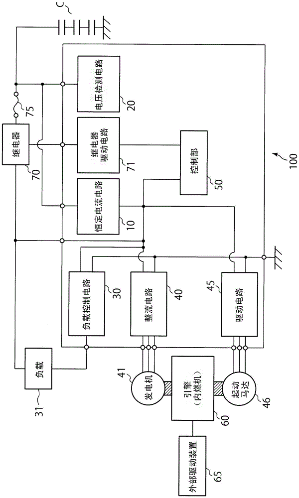
[0023] figure 1 It is a figure for demonstrating embodiment of this invention.

[0024] The internal combustion engine control circuit 100 in this embodiment is a circuit for controlling the engine (internal combustion engine) 60 . Such as figure 1 As shown, the internal combustion engine control circuit 100 in this embodiment is connected to a capacitor C capable of storing electric power, a generator 41 capable of generating electricity, a starter motor 46 for starting the engine 60 , and a load 31 such as a lamp. In this embodiment, no storage battery is used, and only the capacitor C stores electric power, and only the capacitor C is charged by the electric power generated by the generator 41 . On the other hand, the electric power charged to the capacitor C is supplied to the load 31, the starter motor 46, etc. connected to the capacitor C, and these loads 31, the starter motor 46, etc. are driven.

[0025] The internal combustion engine control circuit 10...

Embodiment approach 2

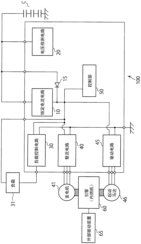
[0052] Second, use figure 2 Embodiment 2 of the present invention will be described.

[0053] In the first embodiment, the relay 70 and the constant current circuit 10 are connected in parallel between the generator 41 and the capacitor C. On the other hand, in this embodiment, such a relay 70 is not provided, and instead the control unit 50 controls the magnitude of the constant current generated by the constant current circuit 10 based on the voltage of the capacitor C detected by the voltage detection circuit 20 . In addition, in this embodiment, a diode 15 connected in parallel with the constant current circuit 10 is provided between the generator 41 and the capacitor C, and the cathode (cathode) of this diode 15 is connected to the generator 41, and the anode (anode) is connected to the capacitor C. C is connected.

[0054] In the second embodiment, the other configurations are substantially the same as those in the first embodiment. exist figure 2 In the second em...


PUM


Abstract

A control circuit for internal combustion engine (100) controls an internal combustion engine (60). The control circuit for internal combustion engine (100) comprises: a voltage detection circuit (20) for detecting the voltage of a capacitor (C) which charges itself with the power generated by a generator (41) that generates power using a driving force generated by the internal combustion engine (60) and a driving force generated by driving an external drive device (65), and supplies a cell motor (46) with the power stored therein; and a control unit (50) for charging only the capacitor (C) by controlling the power supplied from the generator (41) to the capacitor (C) on the basis of the voltage of the capacitor (C) detected by the voltage detection circuit (20). The internal combustion engine (100) further comprises a constant current circuit (10) that connects to the generator (41) and the capacitor (C) to generate a constant current from the current generated by the generator (41), and thus charges only the capacitor (C) with the constant current.

Description

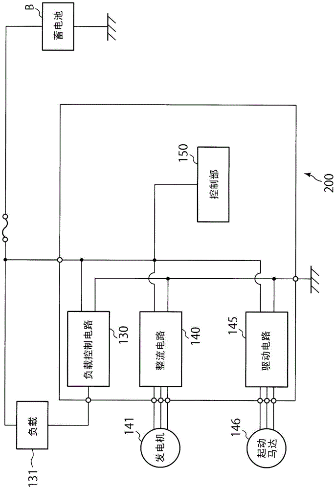
technical field [0001] The invention relates to an internal combustion engine control circuit and an internal combustion engine control method for controlling the internal combustion engine. Background technique [0002] Conventionally, it is known that a capacitor (capacitor) is used in addition to a battery (for example, refer to Japanese Patent Laid-Open No. 2010-083178, Japanese Patent Laid-Open No. 2011-047380 No., Japanese Patent Laid-Open No. 2010-259147 and Japanese Patent Laid-Open No. 2009-180125). It is also known that an internal combustion engine such as an engine is started by driving an external drive device such as a kick starter of a two-wheeled vehicle when the starter motor cannot be started due to low battery voltage. [0003] In addition, as a system using a storage battery, there are image 3 system described in . Such as image 3 As shown, the internal combustion engine control circuit 200 connected to the battery B includes: a load control circuit 1...

Claims


Application Information

Patent Timeline
Patent Type & Authority Patents(China)
IPC IPC(8): H02J7/00
CPCH02J1/06H02J7/14H02J7/345H02J2310/46
Inventor 岡本章広新井逹也
Owner SHINDENGEN ELECTRIC MFG CO LTD
Learn More