
Fixing structure of positioning locking steel plate for proximal femur

A technology for a proximal femur and a fixed structure, applied in the field of medical devices, can solve the problems of affecting the fixation effect, discount of the fixation effect, limited space for the femoral head, etc., and achieve the effects of being conducive to reconstruction, saving installation space, and stabilizing the fixation effect.

Active Publication Date: 2015-11-11
SUZHOU KANGLI ORTHOPEDICS INSTR
View PDF4 Cites 4 Cited by
  • Summary
  • Abstract
  • Description
  • Claims
  • Application Information

AI Technical Summary

Problems solved by technology

The proximal femur locking plate fixation structure in the prior art generally includes: a fixation plate and several screws matched with the fixation plate. Into the femoral body, several screws are arranged in a cross shape in the tuberosity. The defects of this kind of proximal femoral locking plate fixation structure are: 1. Due to the limited space in the tuberosity of the femoral head, several cross screws are installed in the tuberosity. The uplift not only makes the structure more crowded, but also greatly reduces the fixing effect; 2. In the prior art, after the screws are installed in the threaded holes of the fixing steel plate, the screws often loosen as time goes by, which in turn affects the fixing effect

Method used


Image

  • Fixing structure of positioning locking steel plate for proximal femur
  • Fixing structure of positioning locking steel plate for proximal femur
  • Fixing structure of positioning locking steel plate for proximal femur

Examples


Embodiment Construction

[0020] The technical solution of the present invention will be further described below in conjunction with the accompanying drawings.

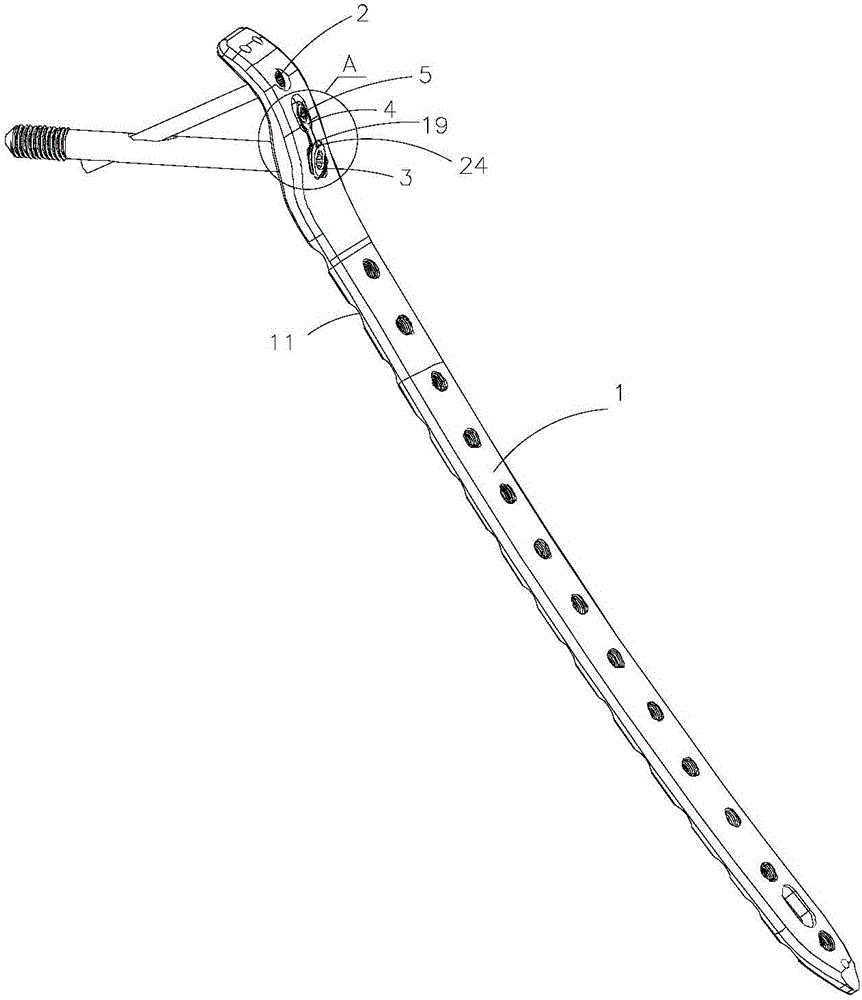
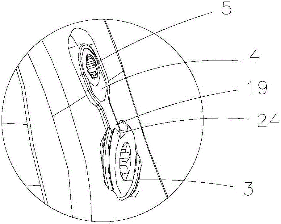
[0021] ginseng figure 1 and figure 2 As shown, a proximal femur positioning and locking plate fixation structure includes: a plate 1, a first screw 2, a second screw 3, a gland 4 and a rivet 5, see image 3 As shown, the steel plate 1 is made of titanium alloy material, and the steel plate 1 includes: a strip-shaped body part 6 and a bending part 7 bent and extended from the strip-shaped body part 6, and the strip-shaped body part 6 is provided with an oval pressure hole 8, a first Kirschner nail fixing hole 9 and thirteen first threaded holes 10, and the bottom side of the elongated body part 6 is provided with several first concave parts 11 The other side of the bottom of the elongated body part 6 is provided with several second recesses (not shown), so that the bending of the steel plate 1 is relatively easy, which is beneficial t...


PUM


Abstract

The invention discloses a fixing structure of a positioning locking steel plate for proximal femur. The fixing structure comprises the steel plate, a first screw, a second screw, a gland and a rivet; the steel plate comprises a long-strip-body portion and a bending portion, the bending portion is provided with second kirschner pin fixing holes, a second threaded hole, a third threaded hole and a gland installing hole, a fourth threaded hole is formed in the gland installing hole, the first screw is installed in the second threaded hole, and the second screw is installed in the third threaded hole; the gland comprises an installing portion and a protruding portion, a rivet installing hole is arranged in the installing portion, and the rivet penetrates through the rivet installing hole to be fixed and clamped in the fourth threaded hole; the second screw comprises a main body portion, a head portion and a tail portion, the head portion of the second screw is provided with a groove which is buckled with the protruding portion of the gland, an inclined hole is formed in the main body portion of the second screw, and the first screw penetrates through the inclined hole. Accordingly, not only is the installing space saved, but also the fixing stability is greatly improved.

Description

technical field [0001] The invention relates to the field of medical devices, in particular to a proximal femur positioning locking plate fixation structure. Background technique [0002] The femur is also called the femur. Violent direct blows, falls from heights, vehicle impacts, rolling, etc. can cause femur fractures. When a femur fracture occurs, the lower limbs cannot move, the fracture site is severely swollen and painful, and deformities such as twisting or angulation may also appear, and sometimes the length of the lower limbs may be shortened. If there is an open wound at the same time, the condition will be more serious and often cause the patient to go into shock. The femur is the largest bone in the whole body. If the fracture is not treated in time, it may cause serious complications such as hemorrhage and nerve damage. The proximal femur locking plate fixation structure in the prior art generally includes: a fixation plate and several screws matched with t...

Claims


Application Information

Patent Timeline
IPC IPC(8): A61B17/80
CPCA61B17/8061A61B17/808A61B2017/564
Inventor 陆军曹刚陈永兵
Owner SUZHOU KANGLI ORTHOPEDICS INSTR
Learn More