
Chemical parallel reaction device

A parallel reaction and chemical technology, applied in chemical/physical/physical-chemical fixed reactors, etc., can solve the problems of complex operation, difficult to achieve, and weak operation ability at the same time, and achieves simple operation, improved automation, and accelerated screening. Effect

Inactive Publication Date: 2015-11-11
ZHENGZHOU UNIV
View PDF4 Cites 9 Cited by
  • Summary
  • Abstract
  • Description
  • Claims
  • Application Information

AI Technical Summary

Problems solved by technology

However, the simultaneous operation of multiple platforms of the existing parallel reactor is weak, the operation is complicated, and it is difficult to realize

Method used


Image

  • Chemical parallel reaction device
  • Chemical parallel reaction device
  • Chemical parallel reaction device

Examples


Embodiment 1

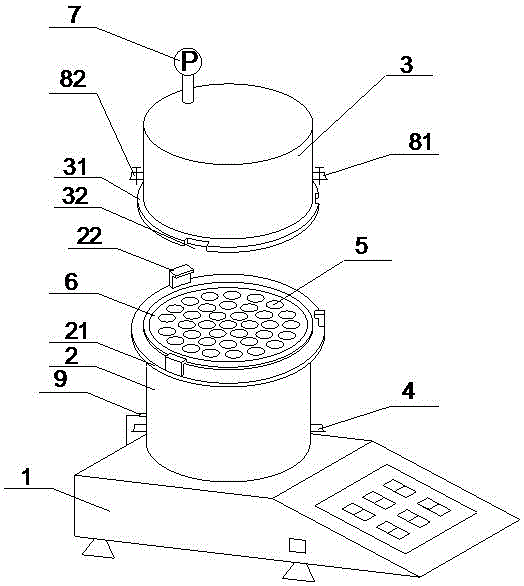
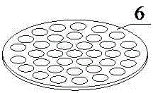
[0021] Such as figure 1 As shown, a chemical parallel reaction device includes a magnetic heating stirrer 1, a heating column 2, and a sealing cover 3. The heating column 2 is placed on the heating panel of the magnetic heating stirrer 1. The upper end of the heating column 2 is integrally formed with an upper The connecting plate 21 and the lower end of the sealing cover 3 are integrally formed with a lower connecting plate 31, and the upper connecting plate 21 and the lower connecting plate 31 are correspondingly provided with a matching positioning block 22 and a positioning groove 32, and the heating column 2 and the sealing cover 3 There is a metal sealing gasket (not shown in the figure) between them, and the heating column 2 and the sealing cover 3 are sealed and connected through the snap fit of the positioning block 22 and the positioning groove 32; wherein, the bottom of the heating column 2 is provided with a condensation The water pipe 4, the middle and lower part ...

Embodiment 2

[0026] A chemical parallel reaction device, the structure of which is basically the same as that of Embodiment 1, and the only difference from Embodiment 1 is that the top of the heating column 2 omits the setting of the reactor column holder 6 .

[0027] This kind of embodiment is applicable to the situation that the reactor is a reactor or similar to it, and the perspective view of the reactor is shown in Figure 4 , sectional view see Figure 5 , the reactor is composed of a kettle body and a kettle cover.

[0028] When a reaction is required, the sealing cover 3 is removed, the required samples and magnets are added to the reaction kettle, and the reaction kettles are placed in the reactor accommodation hole 5 one by one, and then the heating column 2 and the sealing cover 3 are passed through the sealing gasket Sheet, positioning block 22 and positioning groove 32 are sealed and connected. If a reaction with pressure is required, connect the gas cylinder with the requir...


PUM


Abstract

The invention belongs to the technical field of chemical reaction devices, and particularly discloses a chemical parallel reaction device. The device comprises a magnetic heating stirrer, wherein a heating column is placed on a heating panel of the magnetic heating stirrer, and a sealing cover is connected at the upper end of the heating column in a sealing way; wherein a condensate pipe is arranged at the bottom of the heating column in a penetrating way, a thermocouple containing hole is formed in the middle lower part of the heating column, and a plurality of reactor containing holes are formed in the upper part of the heating column; a pressure gauge is arranged at the top of the sealing cover, and an air inlet valve and an air outlet valve are arranged on the side part of the sealing cover; and a thermocouple of the magnetic heating stirrer is placed in the thermocouple containing hole. The chemical parallel reaction device disclosed by the invention is easy to operate, all reaction can be tested simultaneously, heating and stirring can be carried out in each reaction, and each reaction is ensured to carried out independently under the conditions of same temperature, pressure and stirring speed, so that the screening of test conditions and the optimization of reaction conditions are accelerated.

Description

technical field [0001] The invention belongs to the technical field of chemical reaction devices, and in particular relates to a chemical parallel reaction device. Background technique [0002] Parallel reactor is an instrument suitable for micro-scale or small-scale parallel synthesis reactions at low temperature, room temperature, and high temperature. It is suitable for parallel synthesis reactions in open and closed systems, and at the same time ensures the convenience, efficiency, and repeatability of the reaction. , scientific, and created a high-efficiency, high-temperature and low-temperature, high-precision, micro-volume, safe and intelligent response operation platform. However, the simultaneous operation capability of multiple platforms of the existing parallel reactor is weak, the operation is complicated, and it is difficult to realize. [0003] Therefore, a new type of simple parallel reaction device is needed. Contents of the invention [0004] Aiming at t...

Claims


Application Information

Patent Timeline
IPC IPC(8): B01J19/18
Inventor 刘仲毅李卫东李保军苗亚磊李帅辉彭智昆李中军刘寿长
Owner ZHENGZHOU UNIV
Learn More