Aluminum veneer cutting equipment

A technology of cutting equipment and aluminum veneer, which is applied in metal sawing equipment, metal processing equipment, sawing machine devices, etc., can solve the problems affecting the efficiency of aluminum veneer cutting, low degree of automation, and complicated operation, so as to improve safety. high degree of automation, simple and reasonable structure design

Inactive Publication Date: 2015-11-11
天津市帝标建材有限公司
View PDF10 Cites 8 Cited by
  • Summary
  • Abstract
  • Description
  • Claims
  • Application Information

AI Technical Summary

Problems solved by technology

Existing aluminum veneer cutting machines generally require manual assisted feeding, which seriously affects the efficiency of aluminum veneer cutting and processing. At the same time, the manual assisted feeding method is also dangerous
The existing aluminum veneer cutting machine is cumbersome to operate and has a low degree of automation

Method used


Image

  • Aluminum veneer cutting equipment
  • Aluminum veneer cutting equipment
  • Aluminum veneer cutting equipment

Examples


Embodiment Construction

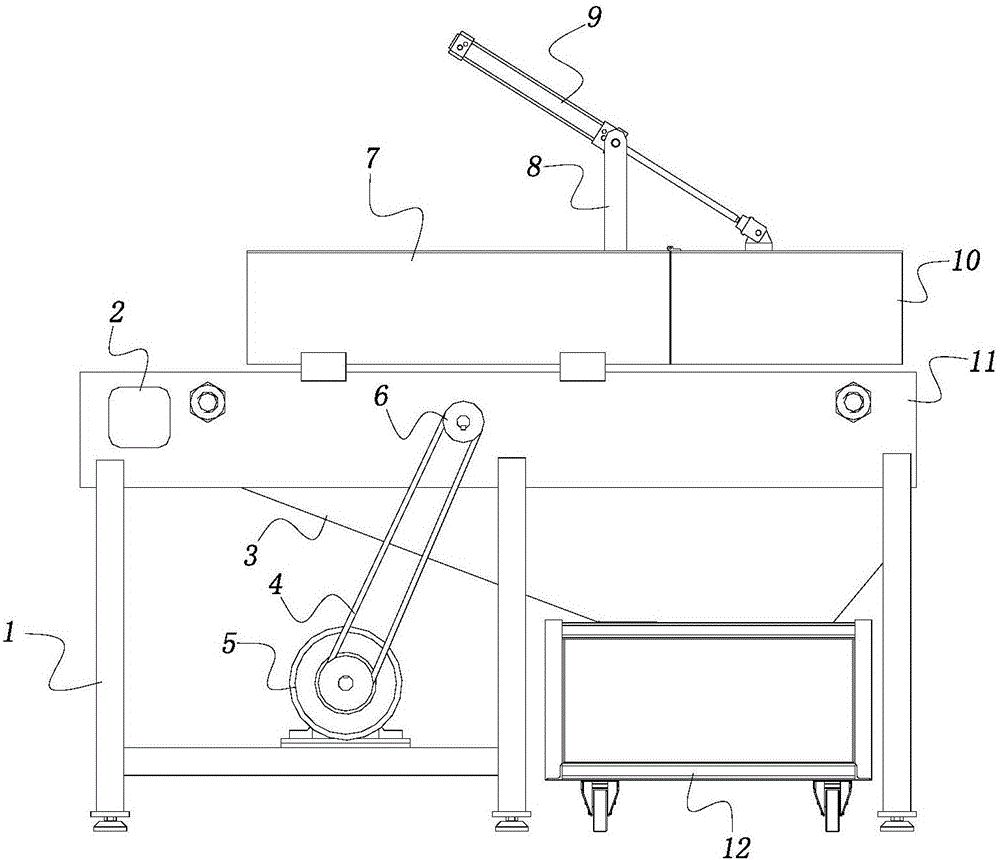
[0013] In order to further understand the content of the invention, characteristics and effects of the present invention, the following examples are described in detail as follows:

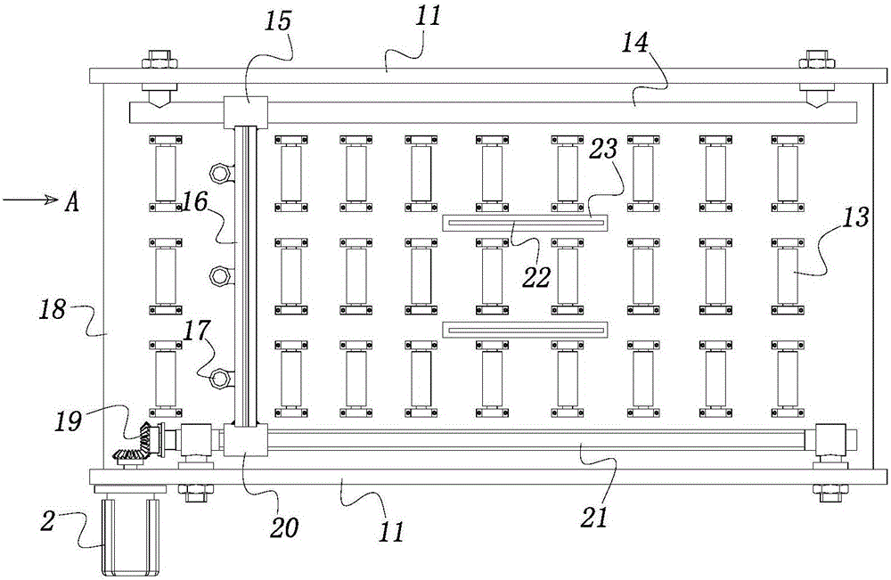
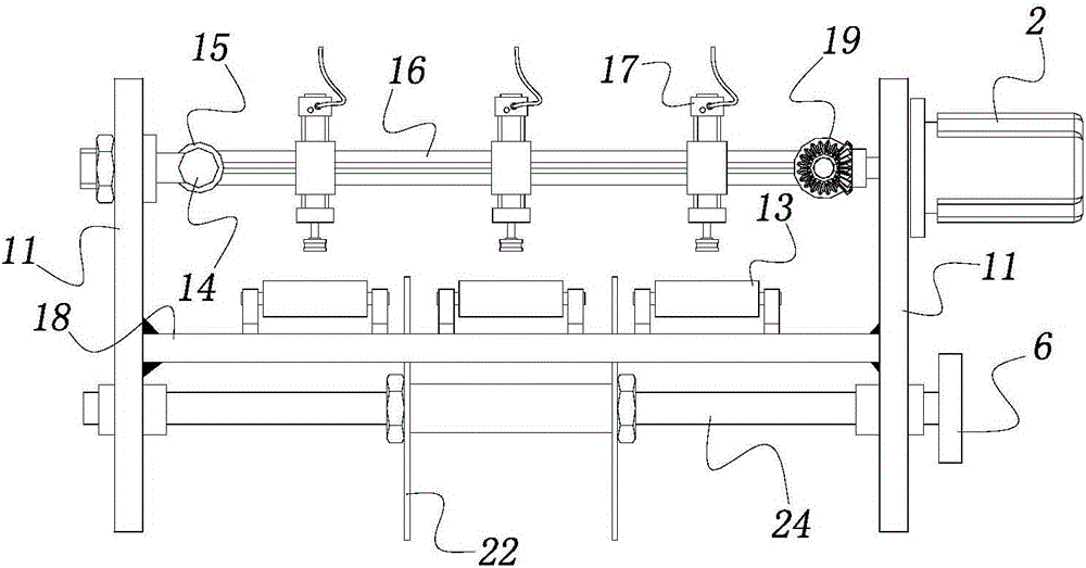
[0014] See Figure 1 to Figure 3 , the present invention includes a feeding and cutting device supported by a plurality of columns 1 .

[0015] The straight bottom plate 18 of the feeding and cutting device is vertically fixed with side plates 11 on both sides of the bottom plate 18 respectively.

[0016] A guide rod 14 with a sliding sleeve 15 is installed on the inside of one of the side plates 11, and a lead screw 21 with a nut 20 is installed on the inside of the other side plate 11. The center line of the guide rod 14 is aligned with the wire. The centerlines of the bars 21 are parallel, and the plane where the centerlines of the two are located is parallel to the upper surface of the bottom plate 18 . The above-mentioned two side plates 11 not only constitute the mounting brackets for the ...


PUM


Abstract

The invention relates to aluminum veneer cutting equipment. The aluminum veneer cutting equipment comprises a feeding cutting device supported by multiple stand columns. The feeding cutting device comprises a straight bottom plate; side plates are perpendicularly and fixedly connected to the two sides of the bottom plate respectively; a guide rod with a sliding sleeve is erected and installed on the inner side of one of the side plates; a lead screw with a nut is erected and installed on the inner side of the other side plate; a first motor for driving the lead screw to rotate is installed on one of the side plate; a cross beam is fixedly erected and connected between the sliding sleeve and the nut; multiple vertical first air cylinders are fixedly installed on the cross beam; a pressure block made of rubber is arranged at the bottom end of a piston rod of each first air cylinder; multiple constant-height supporting rollers are fixedly installed on the upper surface of the bottom plate to form a supporting array; multiple parallel strip-shaped holes are formed in the middle of the bottom plate; a rotary shaft with multiple saw webs in the middle and a driven chain wheel at one end is erected between the middles of the two side plates; the upper edges of the saw webs are located in the strip-shaped holes respectively. The aluminum veneer cutting equipment further comprises a second motor for driving the rotary shaft to rotate.

Description

technical field [0001] The invention belongs to the technical field of plate processing equipment, and in particular relates to an aluminum veneer cutting equipment. Background technique [0002] In the production and processing of aluminum veneer, the forming of the plate is generally carried out on the cutting machine, and the whole aluminum veneer profile is separated, and the aluminum veneer product of predetermined size is processed. Existing aluminum veneer cutting machines generally require manual assisted feeding, which seriously affects the efficiency of aluminum veneer cutting and processing. At the same time, the manual assisted feeding method also has certain risks. The existing aluminum veneer cutting machine is cumbersome to operate and has a low degree of automation. Contents of the invention [0003] The invention provides an aluminum veneer cutting equipment with simple structure, convenient operation and high degree of automation in order to solve the te...

Claims


Application Information

Patent Timeline
Patent Type & Authority Applications(China)
IPC IPC(8): B23D47/04
Inventor 孙波
Owner 天津市帝标建材有限公司
Why Eureka
Try Eureka