Structure and method for rapid centering of fixed spot welding machine electrode arms

An electrode arm and fixed point technology, which is applied to the structure field of fast centering of electrode arms of fixed spot welding machines, can solve the problems of spatter, low equipment utilization, inconsistent distance adjustment, etc., to ensure the centering of welding electrodes and reduce electrode consumption. , The effect of improving the quality of solder joints

Active Publication Date: 2015-11-11
DIGITAL DIE STAMPING TECH WUHAN
View PDF6 Cites 5 Cited by
  • Summary
  • Abstract
  • Description
  • Claims
  • Application Information

AI Technical Summary

Problems solved by technology

[0002] The fixed spot welder is equipment used for welding. A fixed spot welder can produce various types of products. However, in the process of producing different types of products, it is necessary to replace the electrode handle and adjust the distance many times, and because the upper and lower electrodes The arms are individually adjustable, and there is no uniform reference, which leads to inconsistent distance adjustment in the X direction (horizontal direction). The Y direction (vertical) of the electrode arm is 360-degree rotation, and there is no reference reference, which leads to visual reference during the adjustment process. , after locking, the Y direction of the upper and lower electrode handles is not always on a horizontal line; and it takes more than 30 minutes to adjust the electrode centering each time during the replacement and adjustment process, resulting in low equipment utilization and sufficient production capacity. At the same time, because welding requires the end faces of the upper and lower electrodes to be centered, if the end faces are not centered, there will be virtual welding of the welded parts and deformation, spatter, burrs, etc. of the welded parts, resulting in parts that do not meet the requirements and customer complaints

Method used


Image

  • Structure and method for rapid centering of fixed spot welding machine electrode arms
  • Structure and method for rapid centering of fixed spot welding machine electrode arms
  • Structure and method for rapid centering of fixed spot welding machine electrode arms

Examples


Embodiment Construction

[0029] The principles and features of the present invention are described below in conjunction with the accompanying drawings, and the examples given are only used to explain the present invention, and are not intended to limit the scope of the present invention.

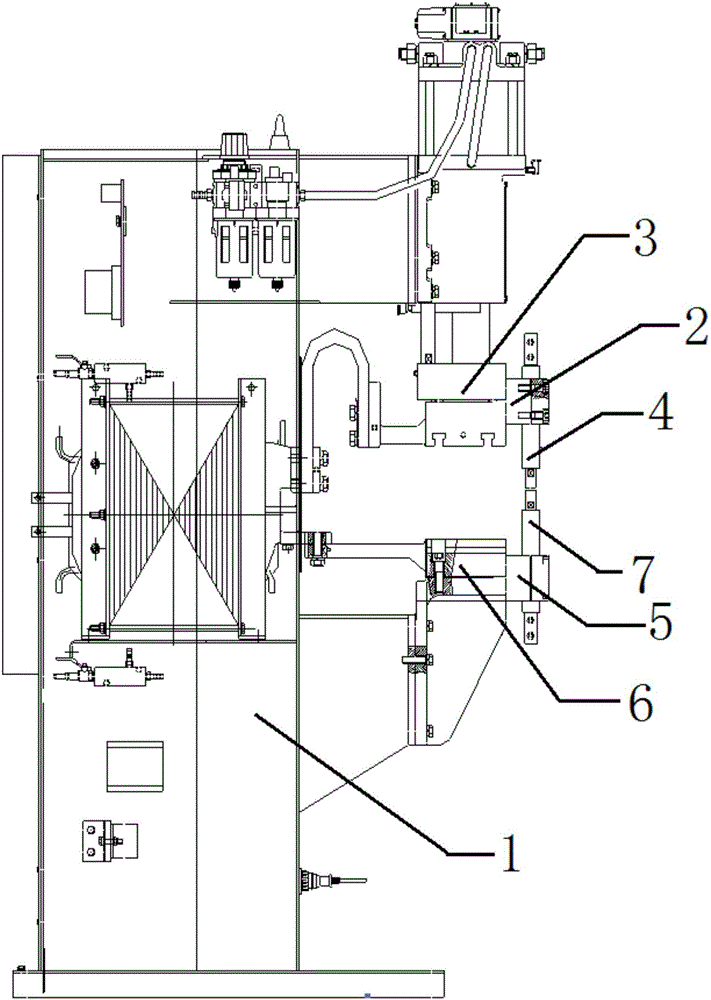
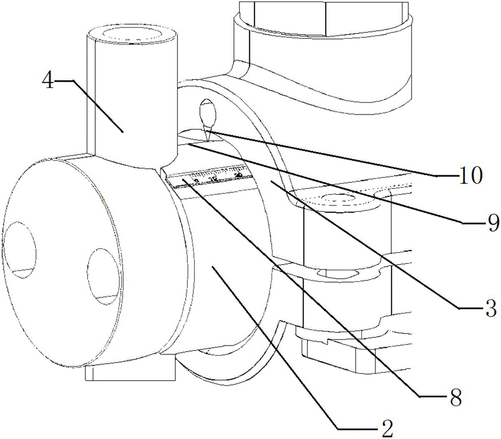
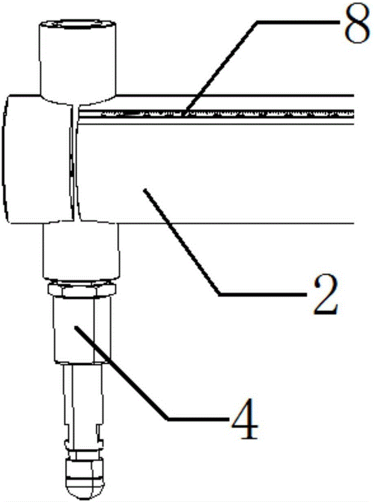
[0030] Such as figure 1 , figure 2 , image 3 , Figure 4 As shown, a structure for fast centering of the electrode arm of a fixed spot welding machine includes a body 1, an upper electrode arm 2, an upper work surface 3, an upper electrode handle 4, a lower electrode arm 5, a lower work table 6 and a lower electrode handle Rod 7, one end of the upper electrode arm 2 is movably installed on the upper work surface 3, the upper electrode holding rod 4 is fixedly installed on the other end of the upper electrode arm 3, and the lower electrode arm 5 One end of which is movably installed on the lower working table 6, the lower electrode handle 7 is fixedly installed on the other end of the lower electrode arm 6, the ...


PUM

PropertyMeasurementUnit
depthaaaaaaaaaa

Abstract

The invention relates to a structure for rapid centering of fixed spot welding machine electrode arms. The structure comprises a machine body, the upper electrode arm, an upper working tabletop, an upper electrode holder, the lower electrode arm, a lower working tabletop and a lower electrode holder. One end of the upper electrode arm is movably installed on the upper working tabletop. The upper electrode holder is fixedly installed at the other end of the upper electrode arm. One end of the lower electrode arm is movably installed on the lower working tabletop. The lower electrode holder is fixedly installed at the other end of the lower electrode arm. The upper electrode arm and the lower electrode arm are each transversely provided with a dividing ruler. The upper electrode arm and the lower electrode arm are each transversely provided with a reference line. The upper working tabletop and the lower working tabletop are each provided with a reference point. In the welding process, the adjusting time for replacing the electrode holders can be shortened, and the production efficiency can be improved; and welding electrode centering is ensured, and the welding spot quality is improved.

Description

technical field [0001] The invention relates to a fixed spot welder, in particular to a structure and method for quickly centering the electrode arm of the fixed spot welder. Background technique [0002] The fixed spot welder is equipment used for welding. A fixed spot welder can produce various types of products. However, in the process of producing different types of products, it is necessary to replace the electrode handle and adjust the distance many times, and because the upper and lower electrodes The arms are individually adjustable, and there is no uniform reference, which leads to inconsistent distance adjustment in the X direction (horizontal direction). The Y direction (vertical) of the electrode arm is 360-degree rotation, and there is no reference reference, which leads to visual reference during the adjustment process. , after locking, the Y direction of the upper and lower electrode handles is not always on a horizontal line; and it takes more than 30 minutes...

Claims


Application Information

Patent Timeline
Patent Type & Authority Applications(China)
IPC IPC(8): B23K11/36
CPCB23K11/36
Inventor 李虎林王玉辉
Owner DIGITAL DIE STAMPING TECH WUHAN
Why Eureka
Try Eureka