
Switching system of sliding rail

A switching system and sliding technology, which is applied in the direction of welding/cutting auxiliary equipment, auxiliary devices, vehicle parts, etc., can solve the problems of cumbersome design, high cost and low efficiency of welding production line, and achieve easy promotion, low manufacturing cost, The effect of simple structural design

Inactive Publication Date: 2015-11-11
ANHUI RUIXIANG IND
View PDF9 Cites 9 Cited by
  • Summary
  • Abstract
  • Description
  • Claims
  • Application Information

AI Technical Summary

Problems solved by technology

[0006] The purpose of the present invention is to overcome the defects of high cost and low efficiency of the current single welding production line, and provide a sliding track switching system. The present invention can realize the collinear production of multiple vehicle models in the same plane, solving the problem of general The cumbersome design of the welding production switching system using the lifting track to switch

Method used


Image

  • Switching system of sliding rail
  • Switching system of sliding rail
  • Switching system of sliding rail

Examples


Embodiment 1

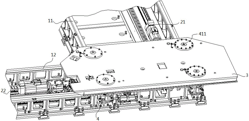
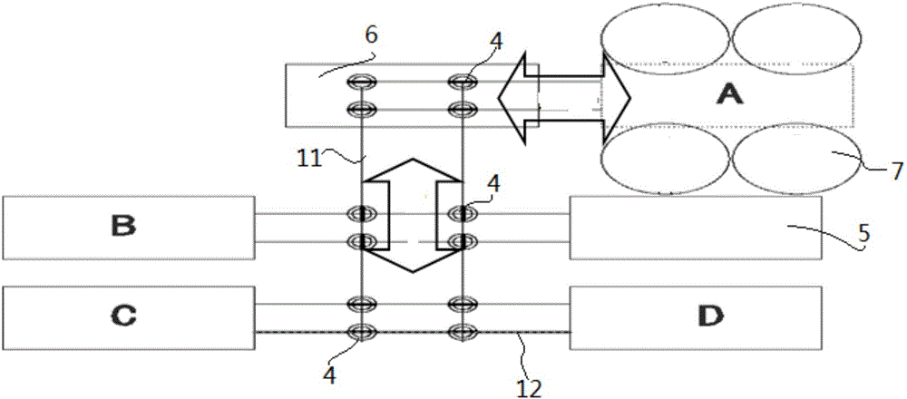
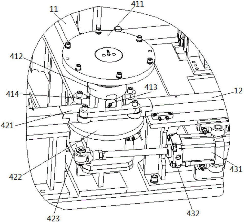
[0026] Such as figure 1 with figure 2 As shown, a sliding track switching system of this embodiment includes a track base, a fixed track group, a servo drive mechanism, a sliding trolley 3 and a single group switching mechanism 4, wherein the fixed track group is arranged on the track base , comprising a Y-direction fixed rail 11 and an X-direction fixed rail 12, and the Y-direction fixed rail 11 and the X-direction fixed rail 12 are mutually vertically distributed; the servo drive mechanism includes a Y-direction drive trolley 21 and an X-direction drive trolley 22, The Y-direction drive trolley 21 is distributed on the inner side of the Y-direction fixed track 11, and the X-direction drive trolley 22 is distributed on the inner side of the X-direction fixed track 12; intersection.

[0027] Wherein the single group switching mechanism 4 comprises a universal support wheel set, a rotating track set and a cylinder driving set, and the universal support wheel set comprises a ...


PUM


Abstract

The invention discloses a switching system of a sliding rail and belongs to the technical field of automobile welding production. The switching system of the sliding rail is characterized by comprising a fixed rail set, a servo drive mechanism, a sliding trolley and single-unit switching mechanisms, wherein the single-unit switching mechanisms are located at the intersecting position of rails of the fixed rail set, and each single-unit switching mechanism comprises a rotating rail set, a universal supporting wheel set and an air cylinder drive set; each rotating rail set comprises a rotating rail, a rotating wheel and a rotating side arm; the two ends of each rotating rail are connected with the rails of the fixed rail set, and each rotating rail is fixedly connected to the corresponding rotating wheel; each rotating wheel is fixedly connected with the corresponding rotating side arm, and the other end of each rotating side arm is hinged to a piston rod of the corresponding air cylinder; each universal supporting wheel set comprises a fixed wheel, a connecting body, a universal sphere and a sliding wheel, and each sliding trolley is fixedly connected with the corresponding fixed wheel; and the sliding wheels are arranged at the lower end of the corresponding universal sphere and clamped on the two sides of the corresponding rotating rail. By means of the single-unit switching mechanism, production of multiple vehicle models on the same line is achieved on the same plane. The switching system of the sliding rail has the beneficial effects of reducing cost and improving efficiency.

Description

technical field [0001] The invention relates to the technical field of automobile welding production, and more specifically relates to a sliding track switching system. Background technique [0002] With the vigorous development of our country's economy and the improvement of people's living standards, more and more cars have entered ordinary families, and the competition point of the car market is more and more concentrated on the upgrading of products. Faced with such a rapid product update, the traditional production mode of a single-model dedicated welding line in the automotive industry is no longer suitable for the current development requirements. How to realize the collinear production of multiple models of automobile welding and reduce production costs to the greatest extent, It has become a major research topic for many manufacturers. [0003] The main task of automobile assembly and welding production is to complete the manufacture of the body. The traditional pr...

Claims


Application Information

Patent Timeline
Patent Type & Authority Applications(China)
IPC IPC(8): B23K37/00
CPCB23K37/00B23K2101/006
Inventor 余子进刘会丙戴荣杰左永会刘泽军叶朝国
Owner ANHUI RUIXIANG IND
Learn More