Blow-molding blank cooling mounting base

A technology of mounting seat and blank body, which is applied in the field of blow molding blank cooling mounting seat, can solve problems such as product failure, and achieve the effect of reducing deformation and temperature

Inactive Publication Date: 2015-11-11
CHONGQING YONGGANG RUBBER & PLASTIC
View PDF0 Cites 2 Cited by
  • Summary
  • Abstract
  • Description
  • Claims
  • Application Information

AI Technical Summary

Problems solved by technology

[0004] The purpose of the present invention is to solve the problem that in the blow molding process of the current blow molding blank after heating or during heating, because the positioning boss is not cooled, the embryo neck is inclined relative to the position of the liquid containing cavity after blow molding, resulting in unevenness of the product. qualified question

Method used


Image

  • Blow-molding blank cooling mounting base
  • Blow-molding blank cooling mounting base
  • Blow-molding blank cooling mounting base

Examples


Embodiment Construction

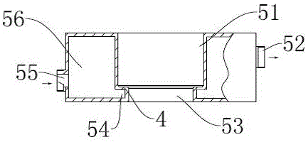
[0019] Such as image 3 Shown is a schematic structural view of the cooling mounting seat of the blow molding embryo body seat of the present invention. The cooling mounting seat of the blow molding embryo body seat is in the form of a cylinder as a whole, and a housing cavity 51 of a cylindrical space is opened on the central axis of the cylinder. The bottom is provided with a through hole 53, and a circulation flow channel is provided between the outer wall of the cooling mounting seat of the blow molding embryo body seat, the accommodation cavity 51 and the through hole 53. Set on the circumference of the through hole 53, the flow channel cavity 56 is also set on the circumference of the receiving cavity 51, the ring cavity 54 communicates with the flow channel cavity 56, and there is an outwardly protruding inflow under the left side wall of the flow channel cavity 56. The mouth 55 is provided with an outwardly protruding outlet 52 above the right side wall of the runner c...


PUM


Abstract

The invention discloses a blow-molding blank cooling mounting base and relates to a blow-molding blank mounting base. The blow-molding blank cooling mounting base is used for heating a blow-molding blank or cooling the neck of the blank during blow-molding and is characterized by comprising a mounting base body, wherein an accommodating cavity for accommodating the neck of the blank is formed in the mounting base, a through hole is formed in the bottom of the accommodating cavity, a circulating runner is formed among the outer wall of the mounting base body, the accommodating cavity and the through hole, and an inflow opening and an outflow opening which are communicated with the external are formed in the runner. The problem of unqualified products caused by the tilting of the blank neck relative to the liquid accommodating cavity after blow-molding due to the deformation of a positioning boss in the blow-molding process because the blow-molding blank is heated or being heated before the positioning boss is cooled is solved by the blow-molding blank cooling mounting base.

Description

technical field [0001] The invention relates to a blow molding blank installation seat, in particular to a blow molding blank cooling installation seat. Background technique [0002] The traditional processing methods of plastic bottles are generally made by embryo body, heating and blow molding. After the embryo body is formed, the structure is as follows: figure 1 As shown, the molded plastic embryo body includes a cavity embryo body 3, the upper part of the cavity cavity embryo body 3 is used for positioning and positioning and positioning bosses 2 in the blow molding process, and the embryo neck 1 is arranged on the upper part of the positioning boss 2 , the embryo neck 1 is an external thread, the cavity embryo body 3, the positioning boss 2 and the embryo neck 1 are integrally formed; the heating process is to heat the embryo body to be blow-molded, and increase the plasticity of the embryo body by heating; the final Blow molding is to pass air to the aperture on the...

Claims


Application Information

Patent Timeline
Patent Type & Authority Applications(China)
IPC IPC(8): B29C49/64B29C49/42B29C49/78
Inventor 沈永钢
Owner CHONGQING YONGGANG RUBBER & PLASTIC
Why Eureka
Try Eureka